CENTRONIC CABLE INTERFACE
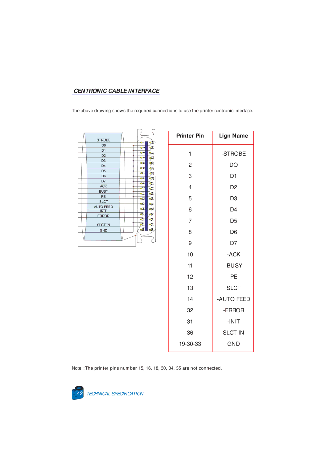
The above drawing shows the required connections to use the printer centronic interface.
Printer Pin | Lign Name |
|
|
1 | |
2 | DO |
3 | D1 |
4 | D2 |
5 | D3 |
6 | D4 |
7 | D5 |
8 | D6 |
9 | D7 |
10 | |
11 | |
12 | PE |
13 | SLCT |
14 | |
32 | |
31 | |
36 | SLCT IN |
GND | |
|
|
Note: The printer pins number 15, 16, 18, 30, 34, 35 are not connected.
![]()
![]() 42
42![]()
![]()
![]() TECHNICAL SPECIFICATION
TECHNICAL SPECIFICATION