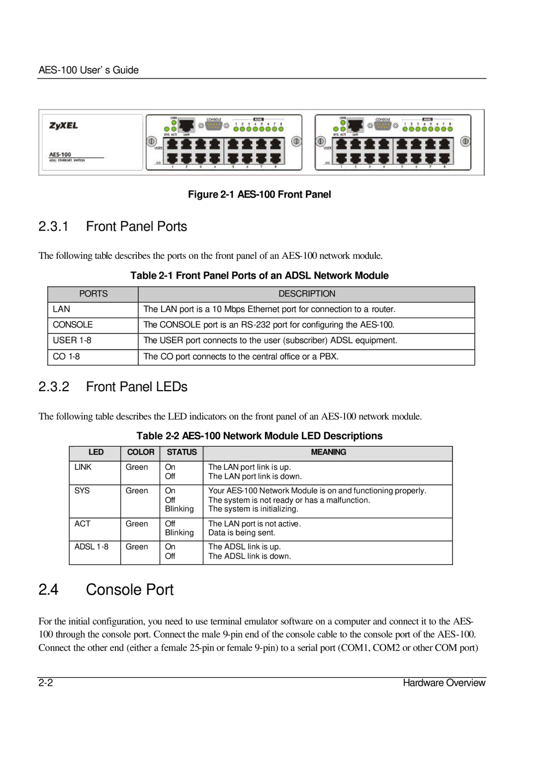
Figure 2-1 AES-100 Front Panel
2.3.1Front Panel Ports
The following table describes the ports on the front panel of an
| Table | |
|
|
|
PORTS |
| DESCRIPTION |
|
|
|
LAN |
| The LAN port is a 10 Mbps Ethernet port for connection to a router. |
|
|
|
CONSOLE |
| The CONSOLE port is an |
|
|
|
USER |
| The USER port connects to the user (subscriber) ADSL equipment. |
|
|
|
CO |
| The CO port connects to the central office or a PBX. |
|
|
|
2.3.2Front Panel LEDs
The following table describes the LED indicators on the front panel of an
Table 2-2 AES-100 Network Module LED Descriptions
LED | COLOR | STATUS | MEANING |
|
|
|
|
LINK | Green | On | The LAN port link is up. |
|
| Off | The LAN port link is down. |
|
|
|
|
SYS | Green | On | Your |
|
| Off | The system is not ready or has a malfunction. |
|
| Blinking | The system is initializing. |
|
|
|
|
ACT | Green | Off | The LAN port is not active. |
|
| Blinking | Data is being sent. |
|
|
|
|
ADSL | Green | On | The ADSL link is up. |
|
| Off | The ADSL link is down. |
|
|
|
|
2.4Console Port
For the initial configuration, you need to use terminal emulator software on a computer and connect it to the AES- 100 through the console port. Connect the male
Hardware Overview |