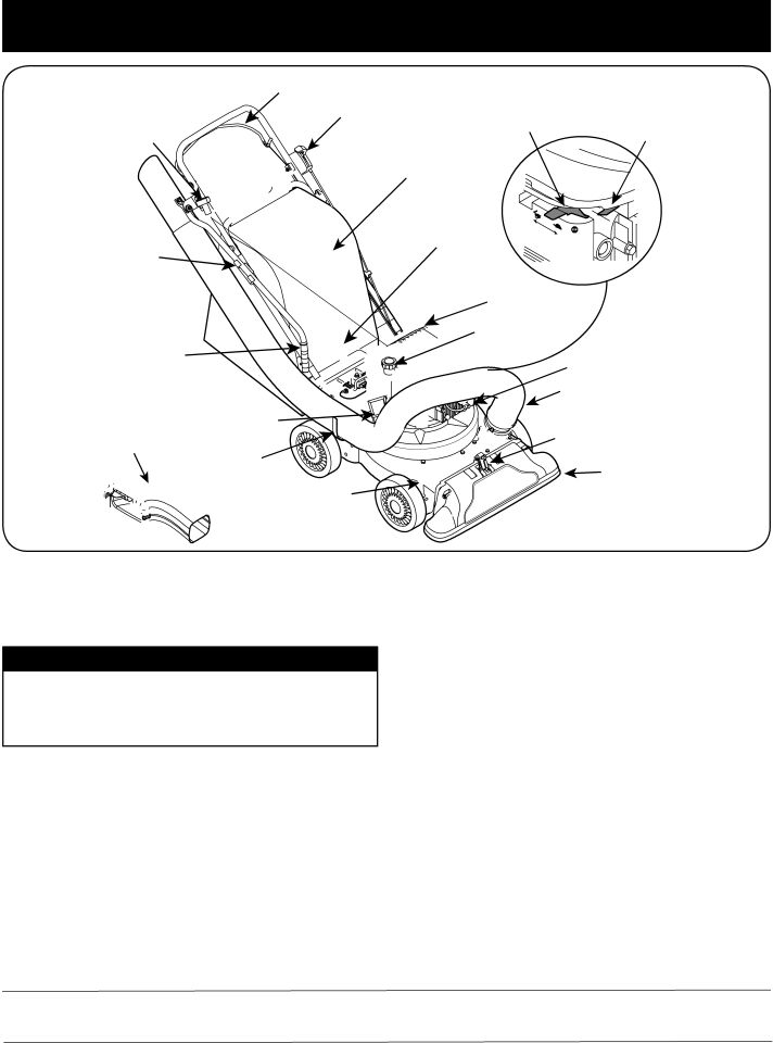
Craftsman 247.77013.0 manual Operation

Page 12


OPERATION


Drive Control

Starter


Speed Control


Throttle Control Choke Control

Handle


Bag

Lower


Bag Handle

Hose Handle


Bracket


Oil Fill


Hose


Gasoline Fill


Spark Plug Wire

Handle


Hose Assembly

† Blower

Chipper

Nozzle/Hose

Chute

Chute

Vac Lever

Hanger Bracket

Nozzle

Nozzle Height


Adjustment Lever

† If Equipped

Figure 10


Now that you have set up your yard vacuum for operation, get acquainted with its controls and features. These are described below and illustrated on this page. This knowledge will allow you to use your new equipment to its fullest potential.

WARNING

The operation of any yard vacuum can result in foreign objects being thrown into the eyes, which can damage your eyes severely. Always wear the safety glasses provided with this unit or eye shields while operating or performing any adjustments or repairs on it.

Chipper Chute

Allows twigs and small branches up to 1-1/2” in diameter to be fed into the impeller for chipping. See Figure 10.

Drive Control

Located on the underside of the upper handle, the drive control is used to engage/disengage wheels. Fully squeeze the drive control against the upper handle to engage the wheels; release to disengage. (DO NOT slip clutch).

IMPORTANT: Move the speed control only when the engine is running. Changing the speed control setting with the engine off can damage the yard vacuum.

Nozzle Height Adjustment Lever

Used to adjust the nozzle ground clearance ranging approximately from 5/8” to 4 1/8”. See Figure 10.

Nozzle

Yard waste such as leaves or pine needles can be vacuumed up through the nozzle for shredding.

Hose Assembly

Used as an alternative to the nozzle to vacuum yard waste such as leaves or pine needles in hard to reach places. See Figure 10.

Nozzle/ Hose Vac Lever

The nozzle/hose vac handle is located on top of the nozzle. Use it to switch vacuum suction between the nozzle and the hose assembly.

Speed Control

Hose Handle

Located on the left side of the upper handle, the speed control is used

Used to guide hose assembly when vacuuming.

to select the forward speed of the yard vacuum.


Meets ANSI Safety Standards

Craftsman Yard Vacuums conform to the safety standard of the American National Standards Institute (ANSI).

12

Image 12
Contents Operator’s Manual Table of Contents WarrantyProduct Specifications Model Number Repair Protection Agreement Safety Instructions TrainingPreparation Maintenance & Storage OperationDo not modify engine This page left intentionally blank Safety Labels To Avoid Serious InjuryAssembly Opening CartonRemoving Unit from Carton Loose Parts in CartonAttaching the Handle Attaching the Hose Assembly Attaching the BAGNozzle Height Adjustment Attaching the Blower ChuteOperation GAS and OIL FILL-UP Attach spark plug wire and rubber boot to spark plug To Start EngineTo Stop Engine To Empty BAGUsing the Nozzle Vacuum Using the Hose AssemblyTo Remove Blower Chute Service and Maintenance Engine MaintenanceServicing the Air Cleaner General RecommendationsClean Equipment LubricationDrive Control Cable Adjustment Removing the Flail ScreenDisconnect and ground the spark plug wire to retaining post Remove bag assembly or blower chuteSharpening or Replacing Chipper Blade Nuts Impeller Maintenance Schedule Gas in the tank † Under heavy load or in high temperaturesEach Use Engine oil level Check OFF-SEASON Storage Preparing the EnginePreparing the yard vacuum Troubleshooting Parts List Description 710-165012 B 21 a 631-0090 Blower Chute 723-0400 Safety Glasses Not Shown  1 11 10Cylinder Assembly Spring-Valve IntakeSpring-Valve Exhaust 694086 Guard-Flywheel691753 Bracket-Air Cleaner Primer 272653†*†† Gasket-Air CleanerHousing-Blower 695161 Cup/Screen Assembly617 270344†*†† Seal-O Ring Intake Manifold Switch-Stop 66538 Boot-Spark PlugCover-Blower Housing Guard-Rewind 498144 Assembly-Pulley/Spring PulleySears Emission Control Defects Warranty Coverage Owner’s Warranty ResponsibilitiesSears Emission Control Defects Warranty Provisions This page applicable in the U.S.A. and Canada onlyPage Índice GarantíaEspecificaciones DEL Producto Número DE ModeloAcuerdo DE Protección Para Reparaciones Instrucciones DE Seguridad CapacitaciónPreparativos Operación Mantenimiento y almacenamientoNo modifique el motor Montaje Apertura DE LA Caja DE CartónCómo Sacar LA Unidad DE LA Caja Piezas Sueltas Dentro DE LA CajaMontaje DE LA Manija Broches de horquilla. Vea la figuraLos pernos del carro deben estar colocados de forma Adecuada en la manija. Vea la figuraInstalación DEL Montaje DE LA MangueraMontaje DE LA Bolsa Instalar EL Canal DE Soplado Ajuste DE LA Altura DEL PicoLibere la palanca hacia la cubierta Operación Llenado DE Gasolina Y Aceite Para Encender EL Motor Para Detener EL MotorDescarga DE LA Bolsa Extracción DEL Canal DE SopladoUSO DEL Pico DE LA Aspiradora USO DEL Montaje DE LA MangueraServicio Y Mantenimiento Recomendaciones GeneralesMantenimiento de Motor Servicio a La BujíaLubricación Limpieza DEL EquipoAjuste del Cable del Control de Transmisiòn Extracción DE LA Pantalla DE DES- GranadoAfilado O Reemplazo DE LAS Hojas DE LA Cortadora Retire el montaje de la bolsa o el canal de sopladoTornillos de cabeza plana Lista DE Mantenimiento Cada Uso Nivel del aceite de motor ComprobarTanque † Bajo carga pesada o en temperaturas altas Almacenamiento Fuera DE Temporada Preparación del MotorLa preparación del vacío de yarda Ya que los motores almacenaron más de 30 díasSolución DE Problemas El motor recalienta El nivel de aceite del motor es bajo Flujo de aire restringidoMotor y alojamiento de soplador Quite la bujía y ajuste el huecoEsta página se aplica sólo en EE.UU. y Canadá Piezas con garantíaMotor certificado Notas MY-HOME1-800-469-4663 Call anytime, day or night