Subaru Robin Power Products R1200 service manual Disassembly and Assembly

Page 32

9. DISASSEMBLY AND ASSEMBLY

9-l PREPARATION AND REMARKS

(1)Be sure to remember the locations of individual parts when disassembling the generator so that the generator can be reassembled correctly. Tie tags with the necessary information written in to facilitate easier and smoother reassembly.

(2)For more convenience, group the related parts and store them in the same box.

(3)To prevent bolts and nuts from being misplaced or installed incorrectly, place them temporarily at their original positions.

(4)Handle the disassembled parts with care and clean them before reassembly using neutral cleaning oil. (Be careful not to clean electric parts with neutral cleaning oil.)

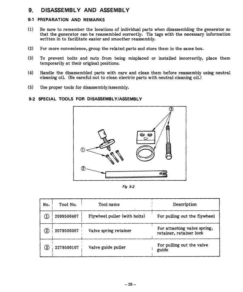
(5)Use proper tools for disassembly/assembly.

9-2 SPECIAL TOOLS FOR DISASSEMBLY/ASSEMBLY

Fig 9-2

No.

i

Tool No. !

Tool name


Description


I

2099500407 1

Flywheel puller (with bolts)


For pulling out the flywheel


!


@

12079500307 i

Valve spring retainer


For attaching valve spring,


retainer, retainer lock


I


For pulling out the valve


2279500107 I

Valve guide puller


i

guide


I


,


- 28 -

Image 32
Contents Rozh -J &ii Foreword Contents Assembly Specifications ItemsPower Factor AC OutputOutput Max Rated 800 W Frequency 50 Hz Voltage 110 Output MaxFrequency 60 Hz Voltage 12ov DC Output Under no load is approximately from 18V up toFeatures Component Identification CHOKE-RUN-STOPFunction of Each Component L-5 4CONNECTING ROD and Piston Main Bearing CoverCrankshaft CamshaftAIR Cleaner Carburetor‘CC Description of Main OperationsVoltage Regulation Under Load Fis Output Waveform Current @ Curr&t @ Operational Limits of the Generator Load Electric Battery Capacity Wire Length Measuring Procedures II ’ Mj 1 mIPage To Measure Insulation Resist Control Panel Functional Check of Each Component L aOne section, replace with Assy 83 AVR Windings, or peripheral temperature Value El 10.7J-z Cleaning of Slip RingResistance At rated rpm Exciting coilDisassembly and Assembly Precautions Tools DriverPrecautions Nection Description SequenceI Part to remove j IFront cover Description I2 Remove the front coverBy unscrewing three M5 x 8 screwsDescription Precautions Part to Sequencej remOveBe careful not to Damage the fuel PipeSpanner Part to Sequence, removeLpanner Remove $Ez End cover Description Precautions @ Driver Remove the connector Assembling, beThat 1wiring Part toRemOve ’Rear ‘bracket Description See Fig. g-3-10’ plastic hammer SequenceI Rpearfito~~ DescriptionPull away the stator cover Siw‘ 13 m/m box Spanner Necessary PrecautionsPart to / Sequencej remove ’ JFront Ibracket Description RemOve DescriptionPrecautions Necessary Tools Blower i 1 1housing I10 m/m box spannerNecessary Precautions . tools @ Driver Precautions Bolt has only to be loosened One M6 x 12 boltBrace nuts 112m/m box ’spanner 10 m/m box jspanner ’Governor Remove the governor lever j Lever26 i &cocci*n Remove the starting pullyIgnition coil from Crank case by takingPull out the intake valve and the exhaust valve Notch Spanner 1spring retainer’sFront and hook ’ the minus driver RetainerCrankcase Tappets to distin Guish them from one ISequenceI Part toCamshaft Description Be careful not to open the joint too wide, or it will break Remove the crankshaft Be careful not toAssembly Procedure WTolerances of new installed parts Connecting rod is joined to the piston with the piston pin Piston and Piston RingConnecting ROD Tappets and CamshaftIntake Valve and Exhaust Valve WV&e h valve guide clearance =53Tappet Adjustment Breather Plate and Tappet Cover Cylinder HeadGovernor Lever Ignition PlugIgnition COIL, Exciting COIL, Flywheel and Starting Pulley Speed Control Nut Muffler and Muffler CoverHead Cover and Blower Housing 1’7 Recoil StartorFront Bracket Rear Bracket and Stator Brash Holder Bracket Cover Page Fuel Pipe Connection Front Cover and Element CoverConnection of Coupler and Plug Secure the side cover with four M 5 x 8 screws Carburetor Schematic Diagram of the Fuel System By-Pass Choke Disassembly and Assembly of Carburetor 184 Safety Precautions Troubleshooting Starting failur Cock is closed Pzlzq L1Ill IISymptoms AIgnition coil ’ \ r?J Hanging posi- tion is not normal Abration 7Symptoms 0Governor system III Seat Case Case there Abnormal Operation Is too much Pour Lubri Been changed Replace Periodically 1Symptoms Voltemeter Stator sub-coil Symptoms LNo DC voltage is output Voltag,eistoo high QParts LSymptoms Symptoms Voltage Is abnormally low Parts For Adjustment Criteria TableUel con Limit Items Adjustment Criteira Description Tools Wiring Diagram LT-TwMaintenance Checks and Maintenance for Every 200 Hours Every Month Page Page Issue EMD-GS0095
Related manuals
Manual 18 pages 8.99 Kb