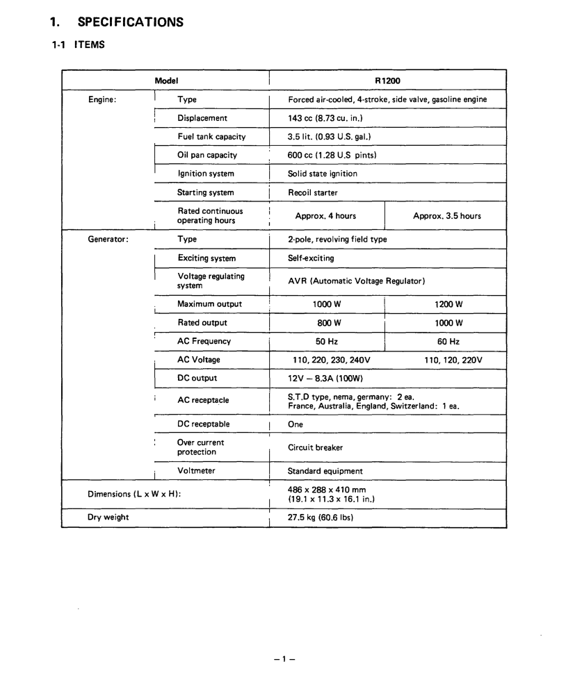
Subaru Robin Power Products R1200 service manual Specifications, Items

Page 5

1.SPECIFICATIONS

l-l ITEMS

Model

Engine:

Type


Displacement

I

Fuel tank capacity

Oil

pan capacity


I

Ignition

system


Starting

system


Rated continuous

I

operating

hours


Generator:

Type


I

Exciting

system


I

Voltage

regulating


system


I

Maximum

output


Rated output


AC

Frequency


AC

Voltage


DC output

I

AC

receptacle

DC receptable

Over current protection

I Voltmeter

Dimensions (L x W x H):

I Dry weight

I

I

,

I

i

I

I

I

I

I

j

I

I

I

!

I

1

I

I

I

R1200

Forced air-cooled, 4-stroke, side valve, gasoline engine

143 cc (8.73 cu. in.)

3.5lit. (0.93 U.S. gal.) 600 cc (1.28 U.S pints) Solid state ignition Recoil starter

I

Approx. 4 hours

Approx. 3.5 hours

2-pole, revolving field type

Self-exciting

AVR

(Automatic

Voltage

Regulator)


1000 w

!

1200 w


800W


I

1000 w


I


50 Hz


1

60 Hz


I


110,220,230,24OV


110,120,220v

12V

-8.3A

(1OOW)


S.T.D type, nema, germany: 2 ea.


France,

Australia,

England,

Switzerland:

1 ea.

One


Circuit

breaker


Standard

equipment


4B6x2BBx410mm


(19.1 x 11.3 x 16.1 in.)


27.5

kg

(60.6 Ibs)


-l-

Image 5
Contents Rozh -J &ii Foreword Contents Assembly Items SpecificationsAC Output Power FactorRated 800 W Frequency 50 Hz Voltage 110 Output Max Output MaxUnder no load is approximately from 18V up to Frequency 60 Hz Voltage 12ov DC OutputFeatures CHOKE-RUN-STOP Component IdentificationFunction of Each Component L-5 Main Bearing Cover 4CONNECTING ROD and PistonCrankshaft CamshaftCarburetor AIR CleanerDescription of Main Operations ‘CCVoltage Regulation Under Load Fis Output Waveform Current @ Curr&t @ Operational Limits of the Generator Load Electric Battery Capacity Wire Length II ’ Mj 1 mI Measuring ProceduresPage To Measure Insulation Resist Control Panel L a Functional Check of Each ComponentOne section, replace with Assy 83 AVR Windings, or peripheral temperature Value El 10.7J-z Cleaning of Slip RingResistance Exciting coil At rated rpmDisassembly and Assembly Driver Precautions ToolsPrecautions Nection Description I2 Remove the front cover SequenceI Part to remove j IFront cover DescriptionBy unscrewing three M5 x 8 screwsPart to Sequencej remOve Description PrecautionsBe careful not to Damage the fuel PipeSpanner Part to Sequence, removeLpanner @ Driver Remove the connector Assembling, be Remove $Ez End cover Description PrecautionsThat 1wiring Part toSee Fig. g-3-10 RemOve ’Rear ‘bracket Description’ plastic hammer SequenceI Rpearfito~~ DescriptionPull away the stator cover Siw‘ 13 m/m box Spanner Necessary PrecautionsPart to / Sequencej remove ’ JFront Ibracket Description RemOve I10 m/m box spanner DescriptionPrecautions Necessary Tools Blower i 1 1housingNecessary Precautions . tools @ Driver One M6 x 12 bolt Precautions Bolt has only to be loosenedBrace nuts 112m/m box ’spanner 10 m/m box jspanner ’Governor Remove the governor lever j LeverRemove the starting pully 26 i &cocci*nIgnition coil from Crank case by takingNotch Spanner 1spring retainer’s Pull out the intake valve and the exhaust valveFront and hook ’ the minus driver RetainerCrankcase Tappets to distin Guish them from one ISequenceI Part toCamshaft Description Remove the crankshaft Be careful not to Be careful not to open the joint too wide, or it will breakAssembly Procedure WTolerances of new installed parts Piston and Piston Ring Connecting rod is joined to the piston with the piston pinTappets and Camshaft Connecting RODIntake Valve and Exhaust Valve =53 WV&e h valve guide clearanceBreather Plate and Tappet Cover Cylinder Head Tappet AdjustmentGovernor Lever Ignition PlugIgnition COIL, Exciting COIL, Flywheel and Starting Pulley Speed Control Muffler and Muffler Cover Nut1’7 Recoil Startor Head Cover and Blower HousingFront Bracket Rear Bracket and Stator Brash Holder Bracket Cover Page Front Cover and Element Cover Fuel Pipe ConnectionConnection of Coupler and Plug Secure the side cover with four M 5 x 8 screws Carburetor Schematic Diagram of the Fuel System By-Pass Choke Disassembly and Assembly of Carburetor 184 Safety Precautions Troubleshooting Starting failur Cock is closed Pzlzq L1Ill IISymptoms AIgnition coil ’ \ r?J Hanging posi- tion is not normal Abration 7Symptoms 0Governor system III Seat Case Case there Abnormal Operation Is too much Pour Lubri Been changed Replace Periodically 1Symptoms Voltemeter Stator sub-coil Symptoms LNo DC voltage is output Voltag,eistoo high QParts LSymptoms Symptoms Voltage Is abnormally low Parts Criteria Table For AdjustmentUel con Limit Items Adjustment Criteira Description Tools LT-Tw Wiring DiagramMaintenance Checks and Maintenance for Every 200 Hours Every Month Page Page Issue EMD-GS0095
Related manuals
Manual 18 pages 8.99 Kb