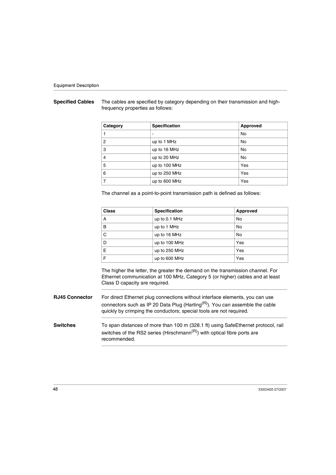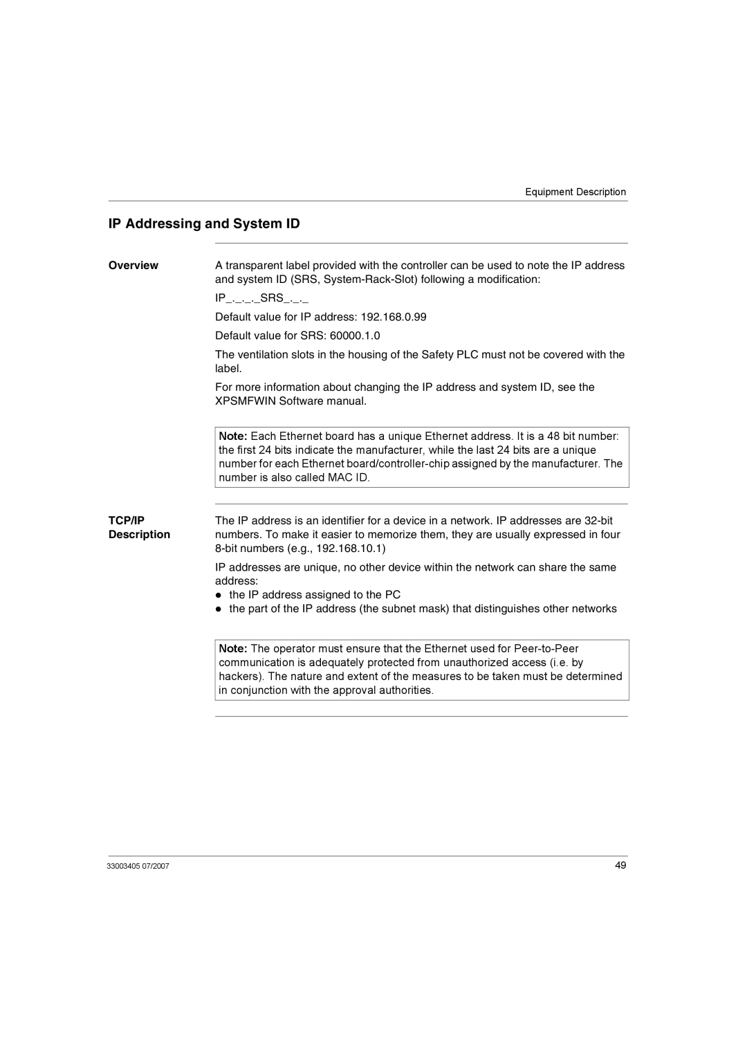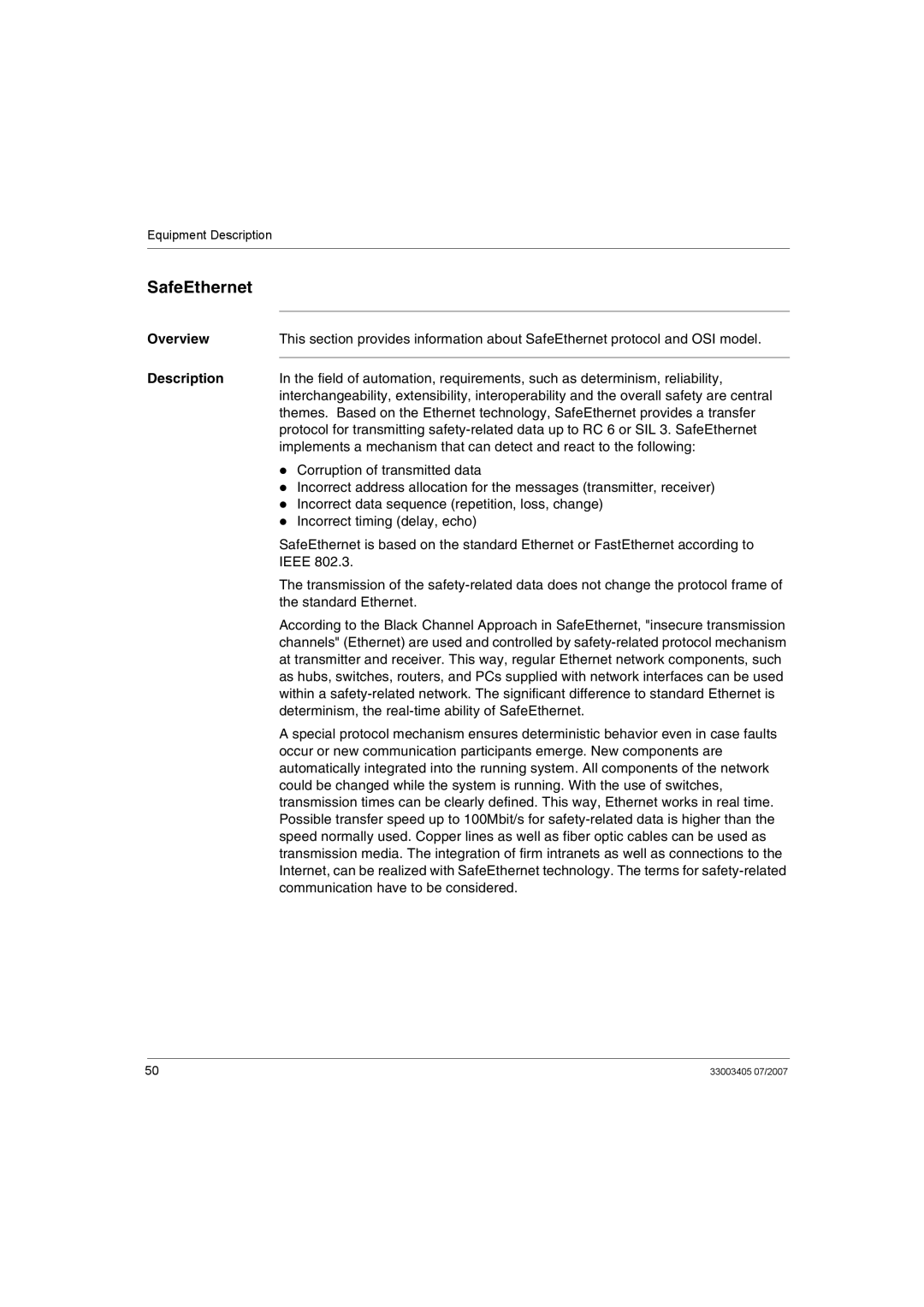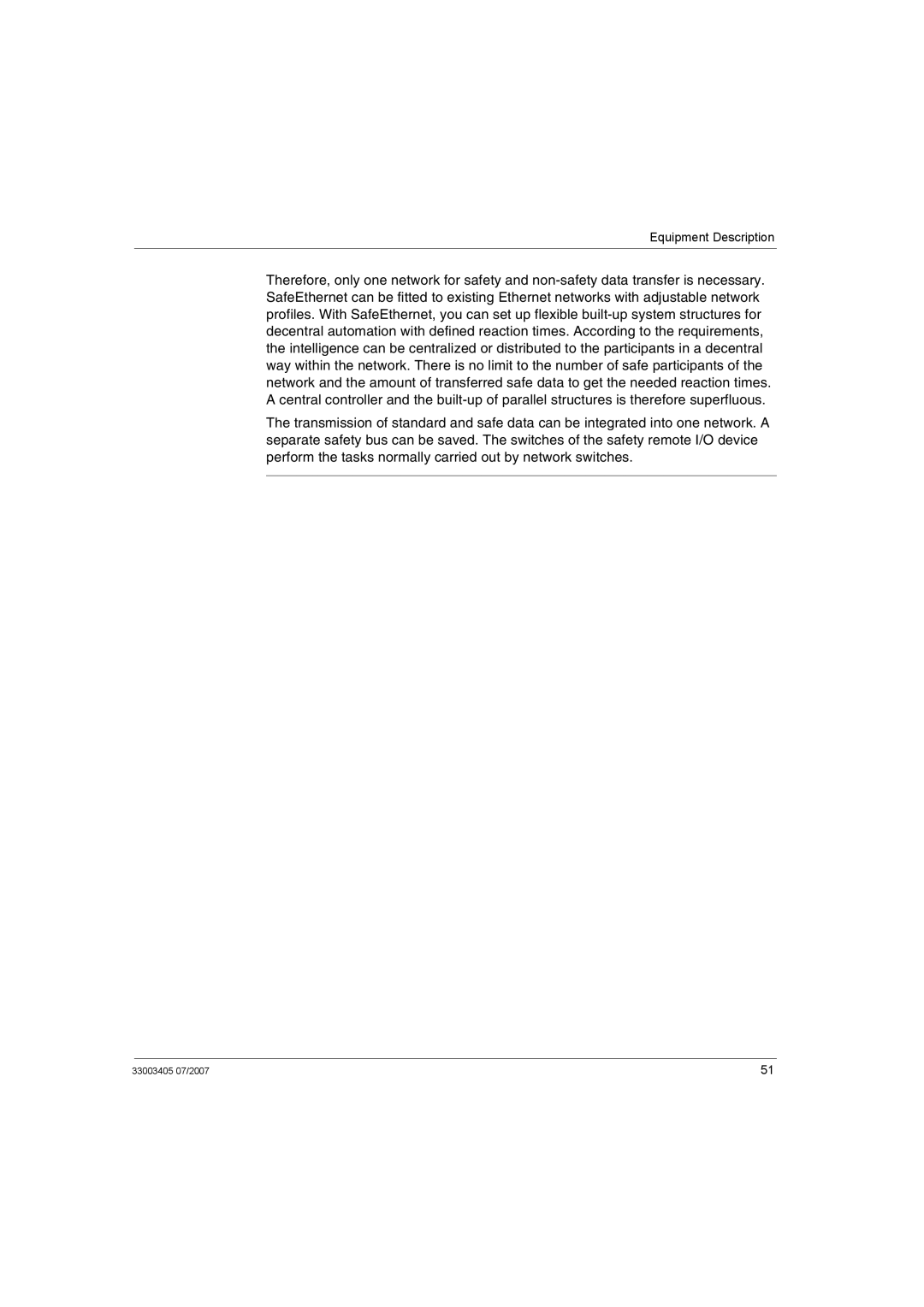
Application and Function
Power Supply Interruption
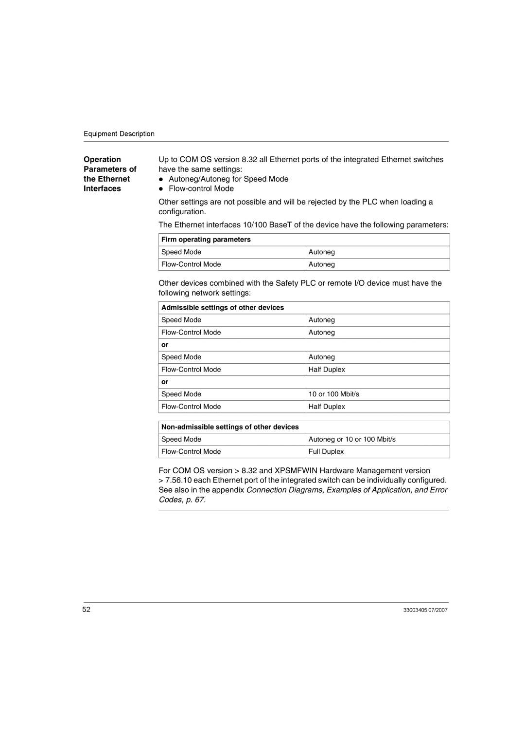
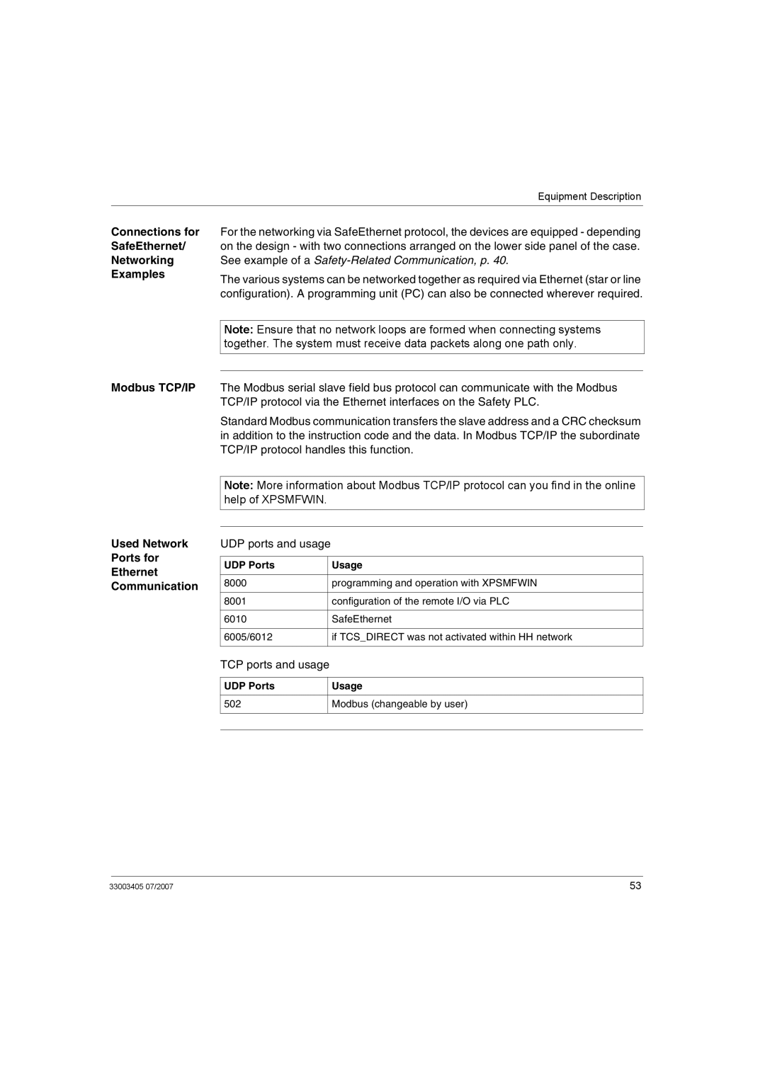
The following table shows reactions to the changes in operating voltage:
Voltage level | Reaction of the controller |
|
|
19.3 to 28.8 VDC | Normal operation |
|
|
< 18.0 VDC | Alarm state (internal variables are written and put to the inputs/ |
| outputs). |
|
|
< 12.0 VDC | Inputs and outputs are switched off. |
|
|
If power supply is interrupted, all inputs and outputs discontinue and return to the off "safe" state.
Small System A Safety PLC can be reconfigured while the network is executing an existing Reconfiguration configuration. Resources which require configuration must be stopped. The following table describes the reconfiguration procedure:
Step | Action |
1Using the XPSMFWIN programming environment, stop the Safety PLC’s system which requires the new configuration.
2Download the new configuration fully checked by a qualified safety engineer to the Safety PLC via Ethernet cable Cat 5, grade D or better.
3Once the module is
4Execute the new configuration immediately.
Large System Reconfiguration
The following table describes the reconfiguration procedure for large systems:
Step | Action |
1Stop the relevant resources within the network using the XPSMFWIN programming environment. Small segments of a network can be reconfigured in stages.
2Connect your PC to any Ethernet communications point.
3Download the new configuration(s) fully checked by a qualified safety engineer to the Safety PLC network via Ethernet cable Cat 5, grade D or better.
4Restart all devices, preferably in stages - system by system.
30 | 33003405 07/2007 |
