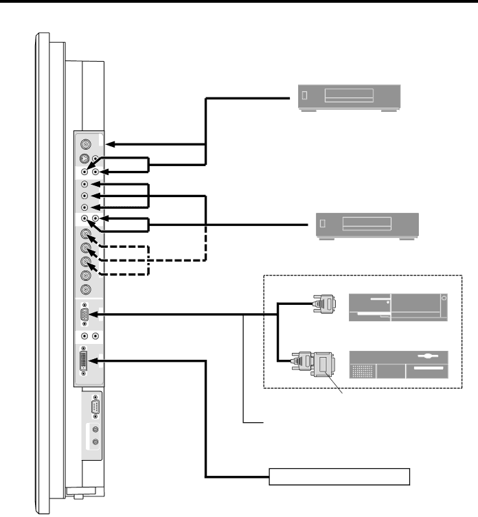
Plasma Monitor Installation
|
|
|
| VCR or Laser Disc Player |
| IN/ | 1VIDEO | VIDEO | VIDEO |
| ) |
| ||
| ( |
|
|
|
| OUT |
|
|
|
VIDEO 3 |
|
| VIDEO 2 | To video inputs on |
|
| the plasma monitor | ||
|
|
|
| |
( |
|
|
|
|
MONO |
| O 1 R |
| |
) | L |
| ||
| b |
| / HD |
|
|
|
| 1 |
|
| r |
|
|
|
( |
|
|
|
|
MONO |
| O 2 R |
| |
) | L |
| ||
| R/ Cr |
|
| |
| G/ Y | RGB | DVD Player | |
| B/ Cb/P | 2 / DVD |
| |
| HD | 2 / HD2 |
| |
| VD |
| IBM VGA or Compatibles | |
| (IN |
| RGB |
|
|
|
| 1 |
|
| ) |
|
|
|
) | L | 3AUDIO R | Macintosh or Compatibles | |
( |
|
|
|
|
MONO |
|
|
| (Desktop type) |
|
|
|
| |
| DVI ( |
| RGB 3 |
|
| RGB ) |
|
| |
|
|
|
| |
| External |
|
| Monitor adapter for |
|
|
| Macintosh | |
| Control |
|
| |
|
|
|
| |
| IN |
|
| To Mini |
| REMOTE |
|
|
|
| OUT |
|
|
|
Signal Source with DVI output
8