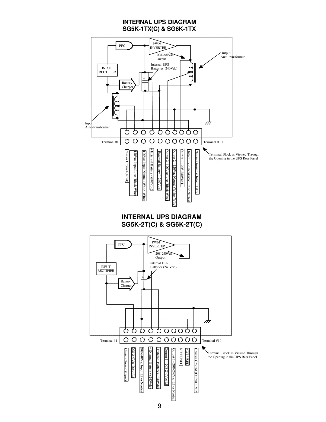
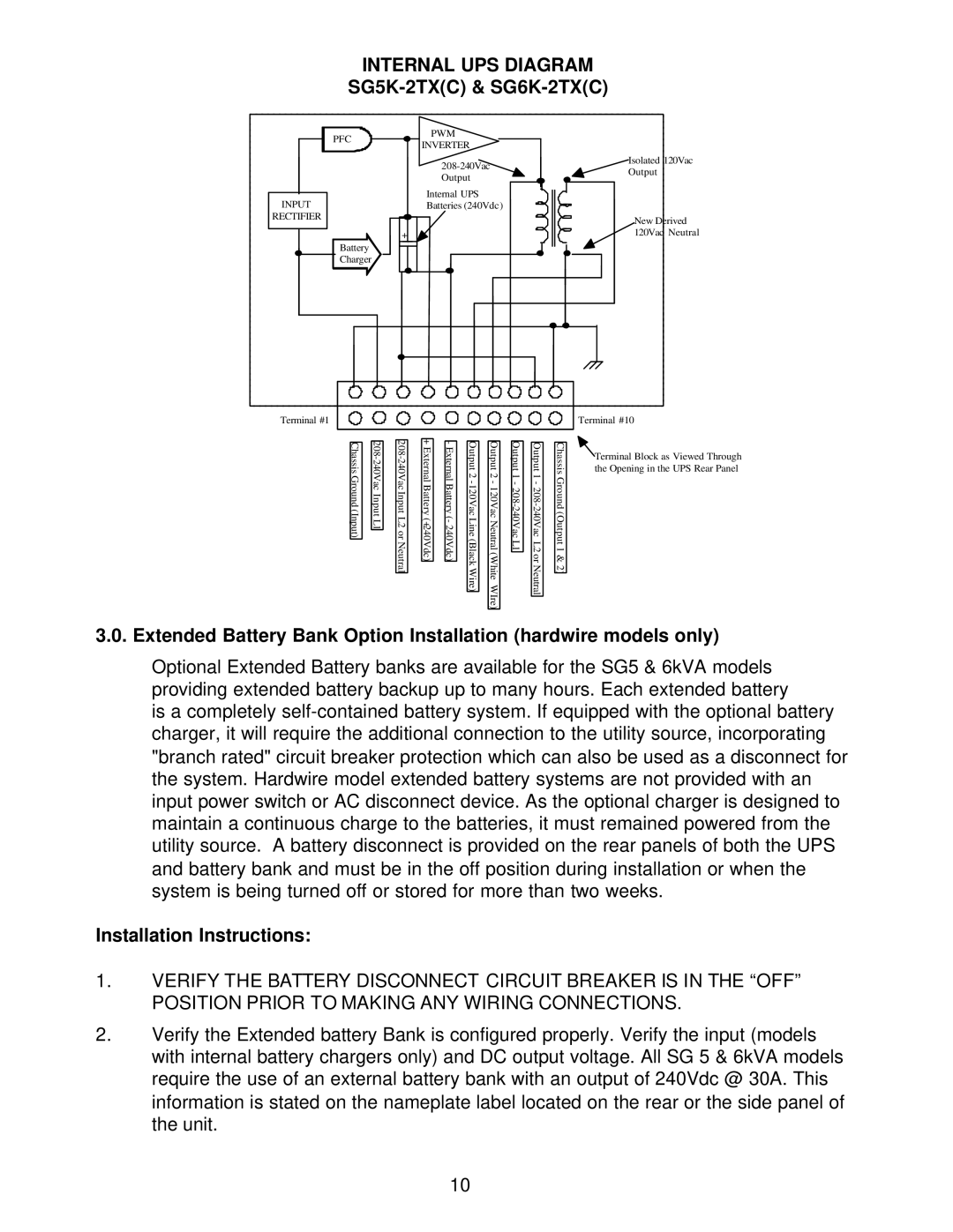
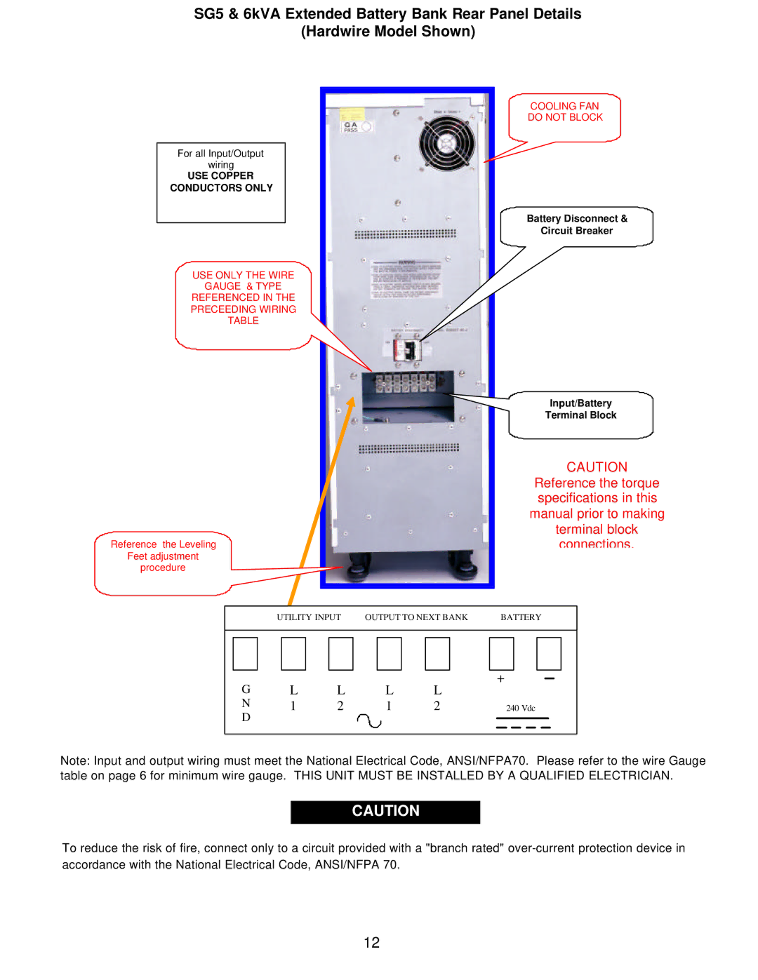
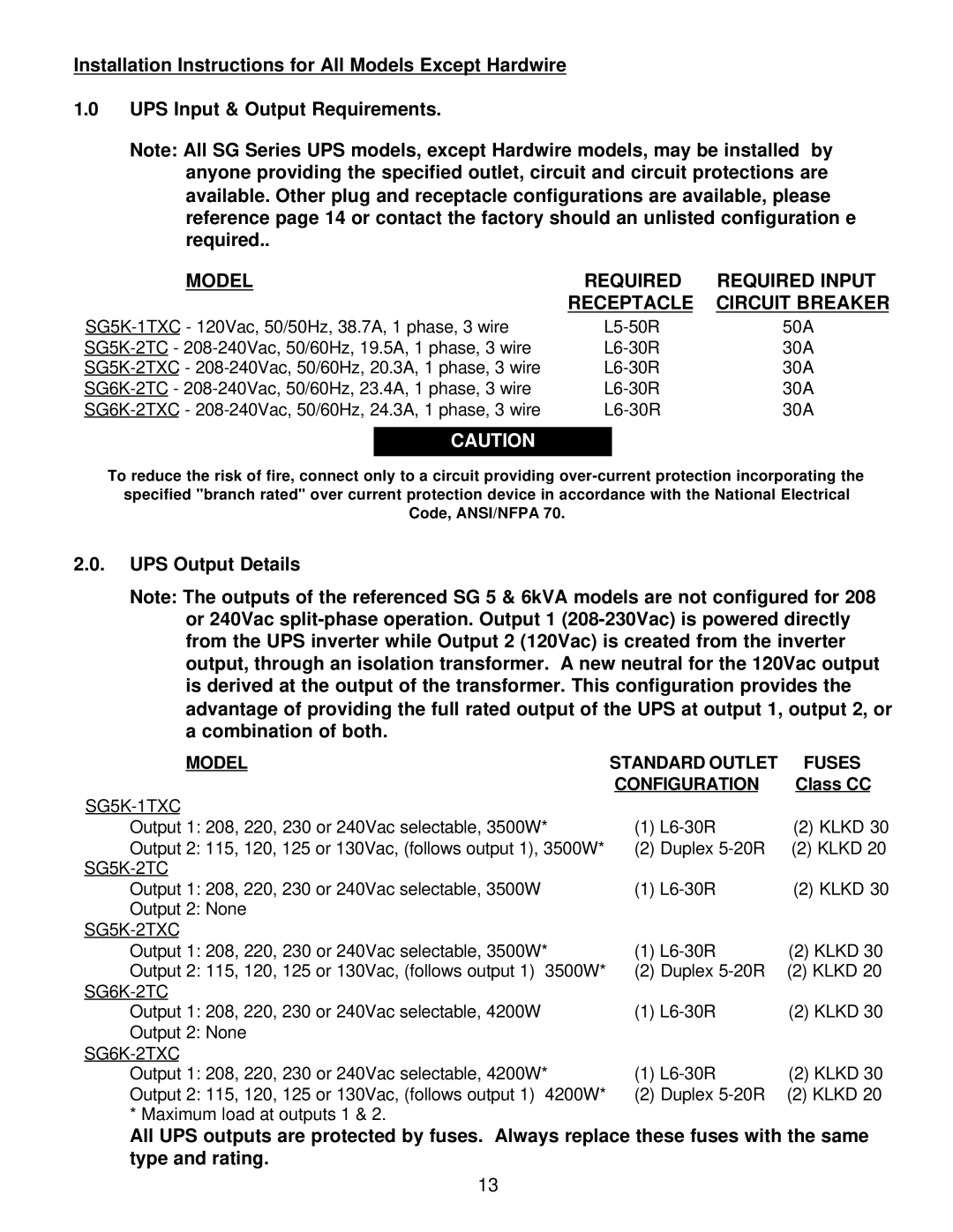
Falcon SG6K-1TX Output Power Distribution Center, Typical Power Distribution Center Configuration

Page 16

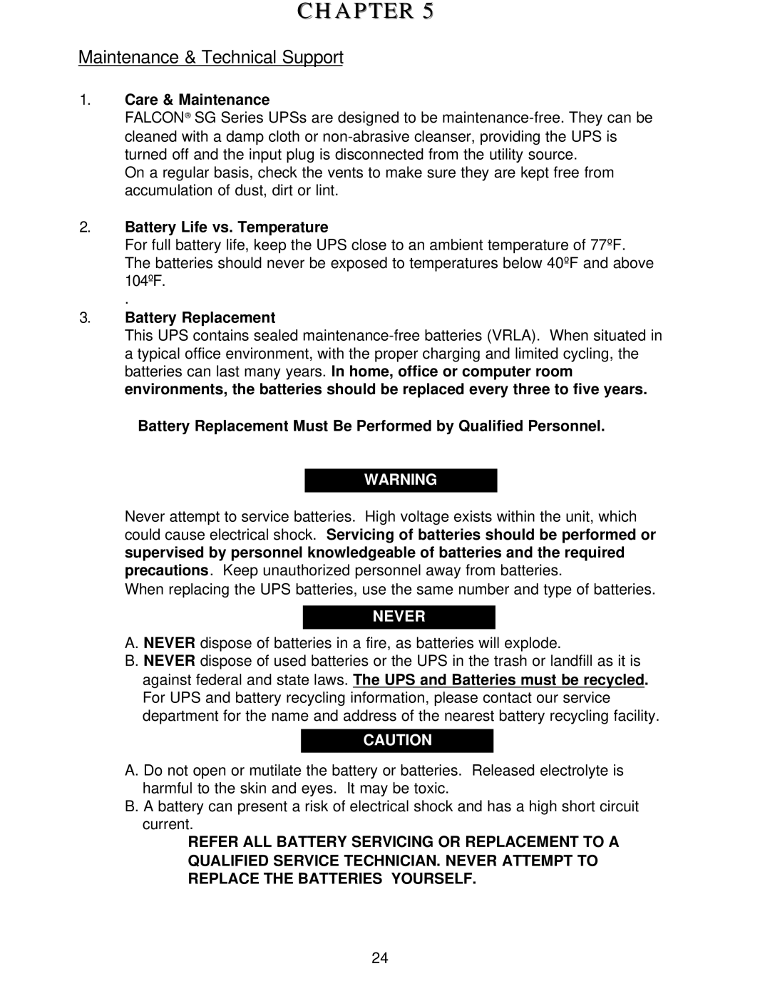
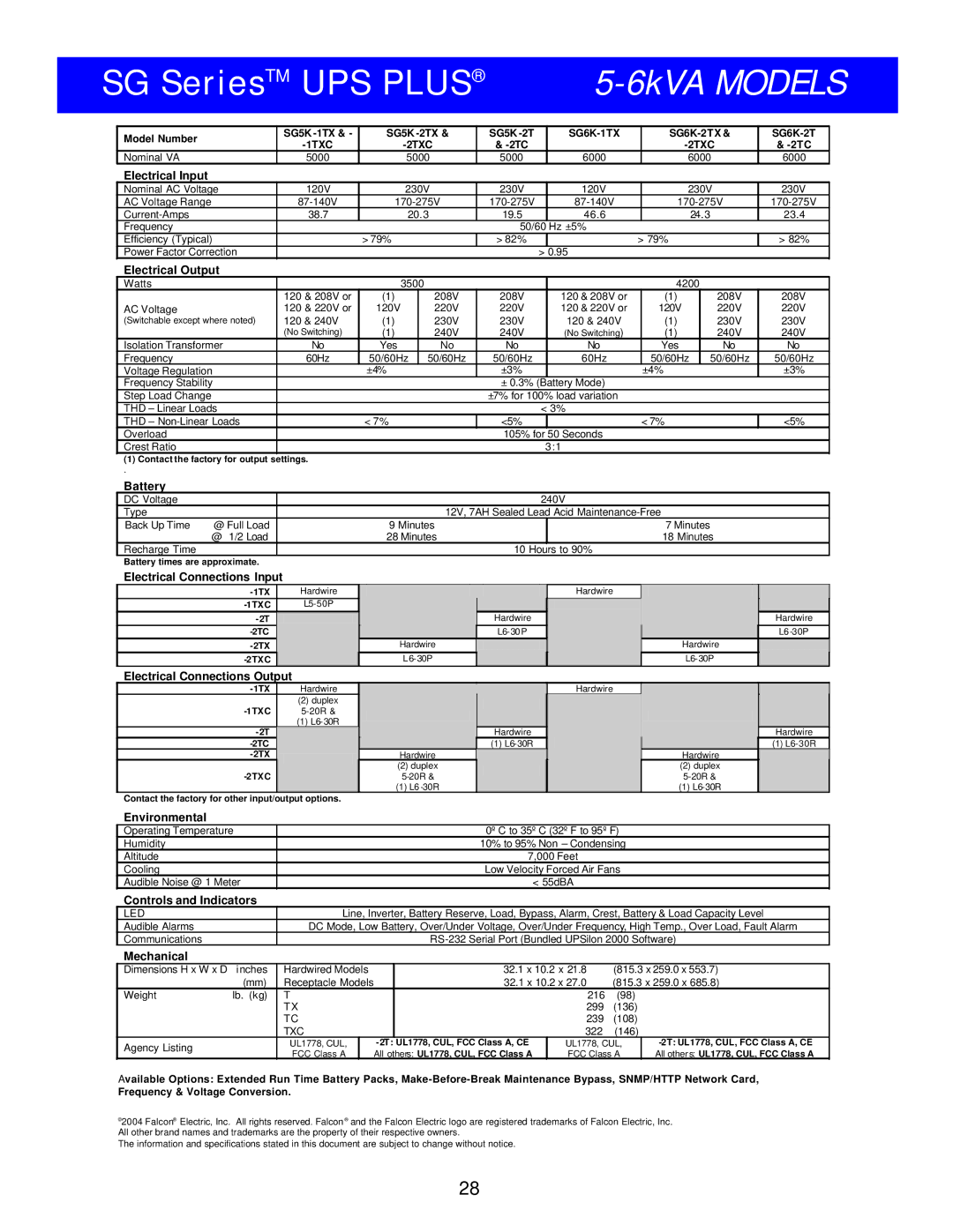
2.1 Output Power Distribution Center

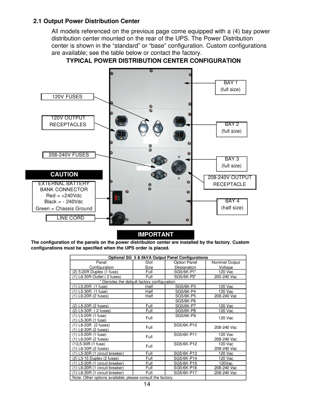
All models referenced on the previous page come equipped with a (4) bay power distribution center mounted on the rear of the UPS. The Power Distribution center is shown in the “standard” or “base” configuration. Custom configurations are available; see the table below or contact the factory.

TYPICAL POWER DISTRIBUTION CENTER CONFIGURATION


BAY 1


(full size)


120V FUSES


120V OUTPUT


RECEPTACLES


BAY 2


(full size)


208-240V FUSES


BAY 3


(full size)


CAUTION


208-240V OUTPUT


EXTERNAL BATTERY


RECEPTACLE


BANK CONNECTOR


Red = +240Vdc


Black = - 240Vdc


BAY 4


Green = Chassis Ground


(half size)


LINE CORD


IMPORTANT

The configuration of the panels on the power distribution center are installed by the factory. Custom configurations must be specified when the UPS order is placed.

Optional SG 5 & 6kVA Output Panel Configurations


Panel

Slot


Option Panel

Nominal Output


Configuration

Size


Designation

Voltage

(2)

5-20R Duplex (1 fuse)

Full


SG5/6K-P1*

120 Vac

(1)

L6-30R Outlet ( 2 fuses)

Full


SG5/6K-P2*

200-240 Vac


* Denotes the default factory configuration.


(1)

L5-20R (1 fuse)

Half


SG5/6K-P3

120 Vac

(1)

L5-30R (1 fuse)

Half


SG5/6K-P4

120 Vac

(1)

L6-20R (2 fuses)

Half


SG5/6K-P5

208-240 Vac


SG5/6K-P6


(2)

L5-20R (2 fuses)

Full


SG5/6K-P7

120 Vac

(2)

L5-30R ( 2 fuses)

Full


SG5/6K-P8

120 Vac

(1)

L5-20R (1 fuse)

Full


SG5/6K-P9

120 Vac

(1)

L5-30R (1 fuse)


(1)

L6-20R (2 fuses)

Full


SG5/6K-P10

208-240 Vac

(1)

L6-30R (2 fuses)


(1)

L5-20R (1 fuse)

Full


SG5/6K-P11

120 Vac

(1)

L6-20R (2 fuses)


208-240 Vac


(1)L5-30R (1 fuse)

Full


SG5/6K-P12

120 Vac

(1)

L6-30R (2 fuses)


208-240 Vac


(1)

L5-30R (1 circuit breaker)

Full


SG5/6K-P13

120 Vac

(2)

L5-15 Duplex (2 fuses)

Full


SG5/6K-P14

120 Vac

(1)

L5-20R (1 circuit breaker)

Full


SG5/6K-P15

120Vac

(1)

L6-20R (1 circuit breaker)

Full


SG5/6K-P16

208-240 Vac

(1)

L6-30R (1 circuit breaker)

Full


SG5/6K-P17

208-240 Vac

Note: Other options available; please consult the factory.


14

Image 16
Contents Owners Operating Manual Table of Contents SG Series ON-LINE UPS System Block Diagram Important Safety Instructions Electric, IncInput Power Factor Correction Extended Battery Bank OptionTrue Regenerative On-Line Design Microprocessor ControlInstallation Instructions General Common for all modelsDisregard On Designation Leveling Feet Adjustment Model View of the Input/Output Hardwire Terminal Block UPS Output RequirementsOutput Requirements Do not USE the Upper Terminal ConnectionsInternal UPS Diagram SG5K-2TC & SG6K-2TCInstallation Instructions SG5K-2TXC & SG6K-2TXCExtended Battery Bank Selection Guide USE Copper Conductors only Receptacle Model RequiredUPS Output Details Output Power Distribution Center Typical Power Distribution Center ConfigurationRefer to page 20 for Operating Instructions All models except hardwire Extended Battery Bank DC InterconnectionInstallation Procedure Load Level Indicator LEDs Battery Level Indicator LEDsLine / Site Wiring Fault Indicator LED Battery Mode Indicator LEDBypass Indicator LED Inverter Indicator LEDGreen Mode LED Indicator Over Crest Indicator LEDCategory one alarms Audible AlarmsCategory two alarms Page Location Communications InterfacesSupported Protocols DRY Contact & Opto Coupler Interface Board Options PIN Assignment for the Falcon Battery Life vs. Temperature Care & MaintenanceBattery Replacement Storing the UPS and Batteries FCC ConsiderationsTechnical Support Requesting Technical Information or SupportSUPPORT@FALCONUPS.COM 800.842.6940 Falcon Web SupportWarranty General Provisions6kVA Models