Lincoln Electric SVM 117-A service manual Thermal Protection

Page 50

Return to Section TOC

Return to Section TOC

Return to Section TOC

Return to Section TOC

Return to Master TOC

Return to Master TOC

Return to Master TOC

Return to Master TOC

E-5

THEORY OF OPERATION

E-5


THERMAL PROTECTION

THERMAL PROTECTION

A thermostat protects the machine from excessive operating temperatures. Excessive operating temper- atures may be caused by a lack of cooling air or oper- ating the machine beyond the duty cycle and output rating. There are three thermostats within the WIRE- MATIC 250 machine. One of the thermostats, located on the output choke, energizes the cooling fan motors when required. The other choke thermostat "opens" the trigger circuit, preventing machine weld output and wire feed, if excessive operating temperatures are detected. The third thermostat insures that the fan motors are operating when required.

The thermostats are self-resetting once the machine cools sufficiently. If the thermostat shutdown is caused by excessive output or duty cycle and the fans are operating normally, the power switch may be left on and the reset should occur within a 15 minute period. If the fans are not turning or the air intake louvers are obstructed, then the input power must be removed and the fan problem or air obstruction be corrected.

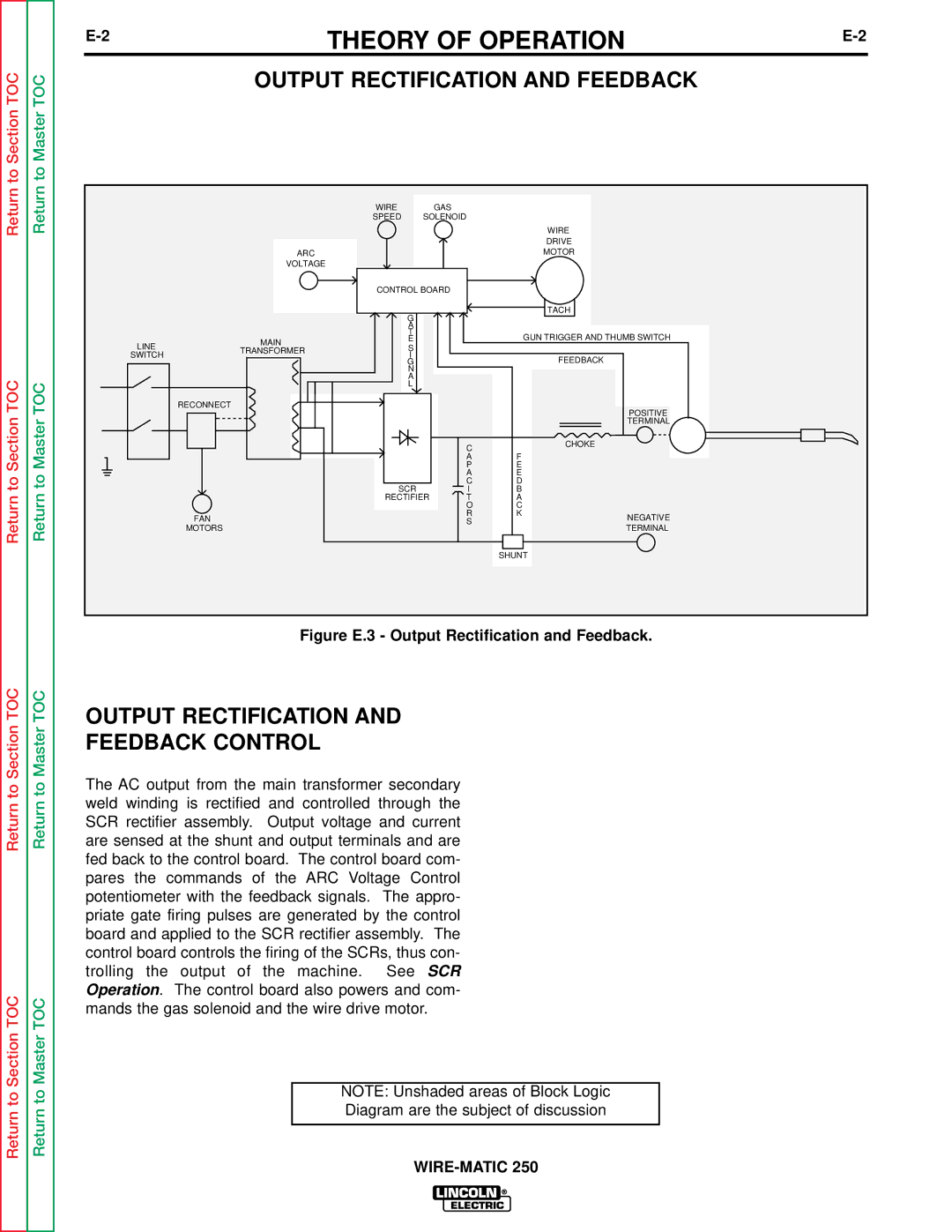
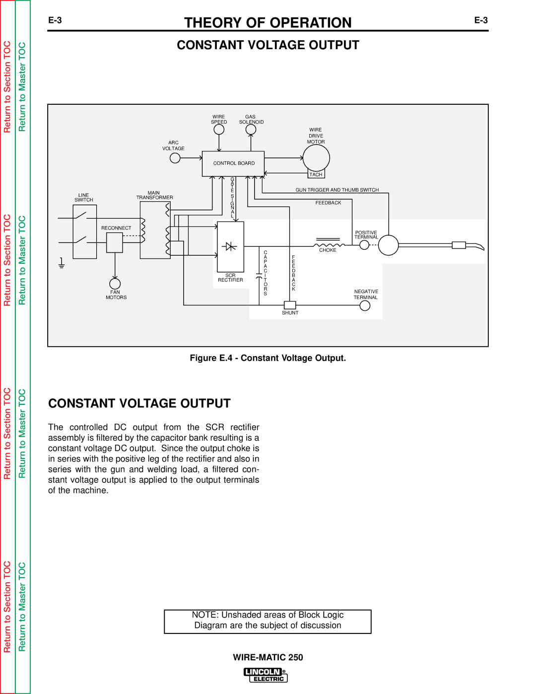
NOTE: Unshaded areas of Block Logic

Diagram are the subject of discussion

WIRE-MATIC 250

Image 50
Contents WIRE-MATIC Safety Depends on YouSafety ARC Welding can be hazardousCylinder may explode if damaged Electric and MAG- Netic Fields IiiPrécautions DE Sûreté Sûreté Pour Soudage a L’ArcWIRE-MATIC Table of Contents Table of Contents Installation Fuse Superlag Duty Cycle Amps Volts at Rated AmpsCurrent Range Type 750C CopperInput Connections Safety PrecautionsSelect Proper Location StackingFuse and Wire Sizes Input Power Connections and Ground ConnectionsConnect Shielding GAS Reconnect Procedure Figure A.4 Input Air Supply ConnectionsFigure A.5 Reconnect Diagram For 208/230/1/60 Machines Connect Output Components GUN Liner and Contact InstallationInstall the Work Clamp Output Polarity ConnectionWire Size Conversion Parts GUN and Cable InstallationWIRE-MATIC Operation WELDING, Cutting Safety InstructionsGeneral Description Power Source Features Design Features AdvantagesUnit Features Recommended Processes and EquipmentLimitations Wire Feeder FeaturesMachine Capability Duty Cycle Amps VoltsControls and Settings Figure B.1 Operator ControlsLoading the Wire Reel Using the Wire Drive RollProcedure for Changing Drive Roll To mount 10 to 30 lb. spools 8 and 12 diameter Proper Wire FeedingFeeding Electrode Starting the Welder Setting Idle Roll PressureOperating Steps Making a Weld WIRE-MATIC Accessories K607-1 Spool GUN Adapter KIT OPTIONS/ACCESSORIESInstalling the K607-1 Spool GUN Adapter KIT Installation Spool GUN Module BoardSpool GUN Connection BOX Installation Return Return to Section TOCSpool GUN Connection Spool GUN PreparationMaking a Weld with the Spool GUN Adapter K607-1 Installed Making the WeldTimer KIT K585-1 Drive Roll Kits Steel Wire Sizes Part NumberAluminum Wire Sizes To Make Spot Plug WeldsMaintenance Routine and Periodic Maintenance Perform the following dailyMaintenance Drive Rolls and Guide Tubes GUN Tubes and Nozzles Contact TIP and GAS Nozzle InstallationCable Cleaning DROP-IN Reel Spindle and ClipsLiner Removal Replacement Figure D.2 Liner maintenanceGUN Handle Disassembly To open up the handleDescription English Size Metric Size WIRE-MATIC Theory of Operation Input Line Voltage and Main TransformerOutput Rectification Feedback ControlConstant Voltage Output Figure E.4 Constant Voltage OutputWire Drive Motor FeedbackThermal Protection SCR Operation Figure E.6 SCR OperationWIRE-MATIC Troubleshooting & Repair HOW to USE Troubleshooting Guide Recommended Course of ActionBoard can be dam- aged by static electricity PC Board Troubleshooting ProceduresElectric Shock can kill Main Transformer Rectifier Assembly Test To Section TOC Perform the SCR Rectifier Perform the Wire Drive Motor Liquid elec Trolyte in these capacitors isPerform the Output Rectifier Materials Needed Main Transformer TestTest Description Main Transformer Test Test Procedure ON/OFF Power Switch will be hot during these testsMain Transformer Test Static SCR Rectifier Assembly Test Leads Figure F.4 SCR 1 Test Points Active SCR Rectifier Assembly Test Leads Figure F.7 SCR Tester Circuit SCR connectionsWire Drive Motor and Tachometer Feedback Test Wire Drive Motor and Tachometer Feedback Test Test Procedure Test for Supply Voltage to Tachometer Test for Feedback Voltage to the Control BoardScope Settings Normal Open Circuit Voltage WaveformMachine Loaded to 250 Amps AT 26 VDC Scope Settings Typical Output Voltage Waveform Machine LoadedMachine Loaded to 220 Amps AT 22 VDC Scope Settings Troubleshooting & Repair Typical SCR Gate Voltage Waveform Materials Needed Control PC Board Removal and ReplacementRemoval and Replacement Procedure Removal and REPLACE- Ment Procedure Wire Drive Assembly Removal and Replacement Wire Drive Assembly Removal and Replacement Procedure Figure F.11 Wire Drive Assembly RemovalSCR Output Rectifier Removal & Replacement Right side heat sink See Figure F.14 Disconnection Heat Sink LeadCapacitor Bank Removal and Replacement Bank Removal Replacement ComponentsMain Transformer Removal and Replacement Power Switch FAN Motor and FAN Removal and Replacement FAN Motor and FAN Removal and Replacement Procedure Figure F.16 Fan Motor and Fan Removal ComponentsTroubleshooting & Repair Input Volts/Hertz Wire Speed RangeOpen Circuit Voltage 230/60 375WIRE-MATIC Table of Contents Electrical Diagrams Section WIRE-MATIC Electrical Diagrams Spool GUN Option Wiring Diagram 208/230 Code To Section Available from Lincoln Control PC Board G2332 Layout