Sterling Plumbing 822.00247.00 specifications Station Alarms, Pump Alarms

Page 35

7-2 Alarms

The format for all station alarms is “Station n [alarm text],” for example, “Station 9 receiver low level.” The format for all pump alarms is “Pump n [alarm text].” Any alarm that does not start with “Station” or “Pump” is a system alarm.

The following tables list all alarms alphabetically, together with possible causes. A “critical” alarm is one that causes the affected device to stop.

Note: You can also see a list of alarms and their causes in the controller’s online help. To display this information, touch the color key of statuses in the upper right-hand corner of either the “Station Status” or the “Pump Status” screen, or touch Help at any other screen. When you are finished reviewing the help, touch Return.

Station Alarms

Alarm message

Possible cause


Material line is blocked.


Vacuum line is blocked.

High vacuum

Convey time is too long (time-fill station only).

Sequence valve has malfunctioned.


Vacuum switch has malfunctioned.


Note: After you have corrected the cause of this alarm, the alarm will be


cleared when the controller has conveyed a full load to this station.


Material container is empty.


Material line is disconnected from material source.

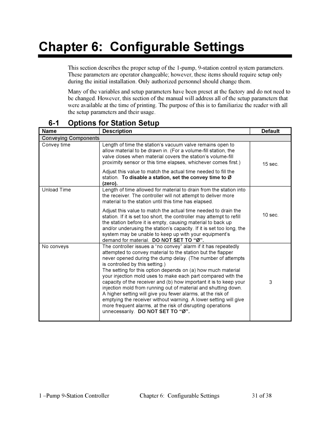
No convey

Vacuum line is disconnected from station.

Take-off compartment is not adjusted properly.


Convey time is too short.


Note: As a stopgap measure, you can disable the “no convey” alarm for


this station until the problem can be remedied.

Pump Alarms

Alarm message

Possible cause

Pump failure

Circuit breaker or overload protector has tripped.

(Critical)

Contactor has malfunctioned.

1 –Pump 9-Station Controller

Chapter 7: Troubleshooting

34 of 38

Image 35
Contents SCC 1-Pump 9-Station Controller Parts and Service Department If the Shipment is Not Complete Shipping InformationUnpacking and Inspection Event of Shipping DamageCredit Returns Warranty ReturnsReturns Table of Contents Configurable Settings Safety Symbols Used in this Manual SafetyHow to Use This Manual Controller Safety Tags Description Wear Safety Glasses and Work Gloves General Responsibility ResponsibilityOperator Responsibility Maintenance ResponsibilityReporting a Safety Defect General Description Functional DescriptionModels Covered in This Manual Controller Features Standard FeaturesMechanical Features Electrical FeaturesFail Safe Operation Optional FeaturesSafety Devices and Interlocks Safety Circuit StandardsSafety Device Lock-Outs Mounting the Control Panel InstallationMaking Control Panel Power Drop Wiring Connections UncratingConnecting the Control Panel to the Pump Package Connecting the Control Panel to Vacuum HoppersActivating and Deactivating the System SetupBasic Menus and Setup of Controller Name Description Viewing System StatusInitial Station Setup Screen Station SetupController Keypad Entering Values Into Controller FieldsSecond Station Setup Screen Third Station Setup Screen Initial Pump Setup Screen Pump SetupSecond Pump Setup Screen Third Pump Setup Screen Initial System Setup Screen System SetupThird System Setup Screen Second System Setup ScreenStarting and Stopping the System AlarmsOperation OverviewFilter Can Pump FaultGeneral Fault All FaultsMaintenance Options for Station Setup Configurable SettingsOptions for Pump Setup General Troubleshooting TroubleshootingPump Alarms Station AlarmsAppendix WarrantyWarranty Specifications Warranty RestrictionsCustomer Responsibilities Warranty LiabilitiesOptional Components Spare Parts List Drawings and DiagramsTechnical Assistance Contact Information Controller Identification Serial Number Tag