5.Specifications
5-1. Ionizer
Ionizer model | IZS31(NPN) | IZS31P(PNP) | |||
|
|
|
|
| |
| Type | Corona discharge | |||
|
|
|
| ||
Voltage supply method | Sensing DC, pulse DC, Plus DC, Minus DC | ||||
|
|
|
| ||
Discharge output | +/- 7000 V | ||||
|
|
|
| ||
Ion balance *1 | |||||
|
|
|
|
| |
|
| Fluid | Air (Clean dry air) | ||
|
|
|
|
| |
|
| Op. pressure | 0.7 MPa or less | ||
Purge air |
| (MPa) | |||
|
|
| |||
|
|
|
|
| |
|
| Connection | Φ4 | ||
|
| tube size | |||
|
|
|
| ||
|
|
|
| ||
Power supply voltage | DC24 V | ||||
|
|
|
|
| |
|
| SensingDCmodeoperated | 200 mA or less (When sensor is standby:120 mA or less) | ||
Current consumption |
|
|
|
| |
| 200 mA or less (When sensor is not used:170 mA or less) | ||||
|
|
|
|
| |
|
| Pulse DC mode | 170mA or less | ||
|
|
|
|
| |
|
| Discharge stop signal |
|
| |
Input signal |
|
| |||
| Maintenance | ||||
|
| signal |
|
| |
|
|
|
|
| |
|
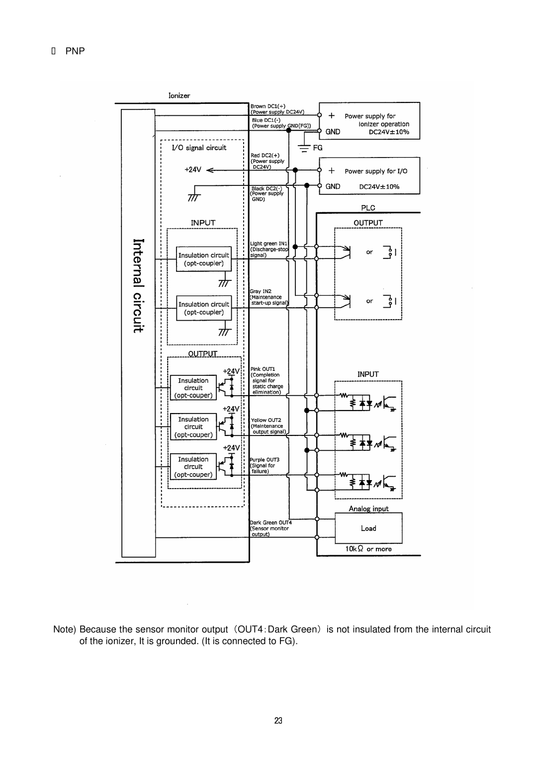
| Completion signal for | Maximum load current : 100mA | Maximum | |
|
| static charge elimination | Residual voltage : 1V or less | load current : 100 mA | |
Output signal |
|
| (when the load current is 100mA) | Residual voltage : 1V or less | |
| Maintenance output signal | ||||
|
|
| Max. applied voltage:DC28V | (With load current of 100 mA) | |
|
| Signal for failure | |||
|
|
|
|
| |
|
| Sensor monitor output*2 | Output voltage: 1 to 5 V (Please connect the load of 10kΩ or more.) | ||
Effective elimination distance | 50 to 2000 mm (with sensing DC mode:200 to 2000 mm) | ||||
|
| ||||
Ambient temperature | 0 to 50 ℃ | ||||
|
| ||||
Ambient humidity | 35 to 80 %Rh(No dew condensation) | ||||
|
|
|
| ||
Material | Ionizer cover:ABS | ||||
Electrode needle:Tungsten, single crystal silicon, stainless | |||||
|
|
| |||
|
|
|
|
| |
Vibration resistance | Endurance 50Hz | Amplitude 1mm | |||
2 hours to X,Y,Z each direction of vibration | |||||
|
|
| |||
|
| ||||
Impact resistance | 10G | ||||
|
|
|
| ||
Applicable standard/ directive | CE (EMC directive:89/336/EEC,92/31/EEC,93/68/EEC,2004/108/EC、 | ||||
Low Voltage Directive:73/23/EEC,93/68/EEC) | |||||
|
|
| |||
|
|
|
|
| |
※1:The distance between the charged object and ionizer is 300mm or more. With air purge.
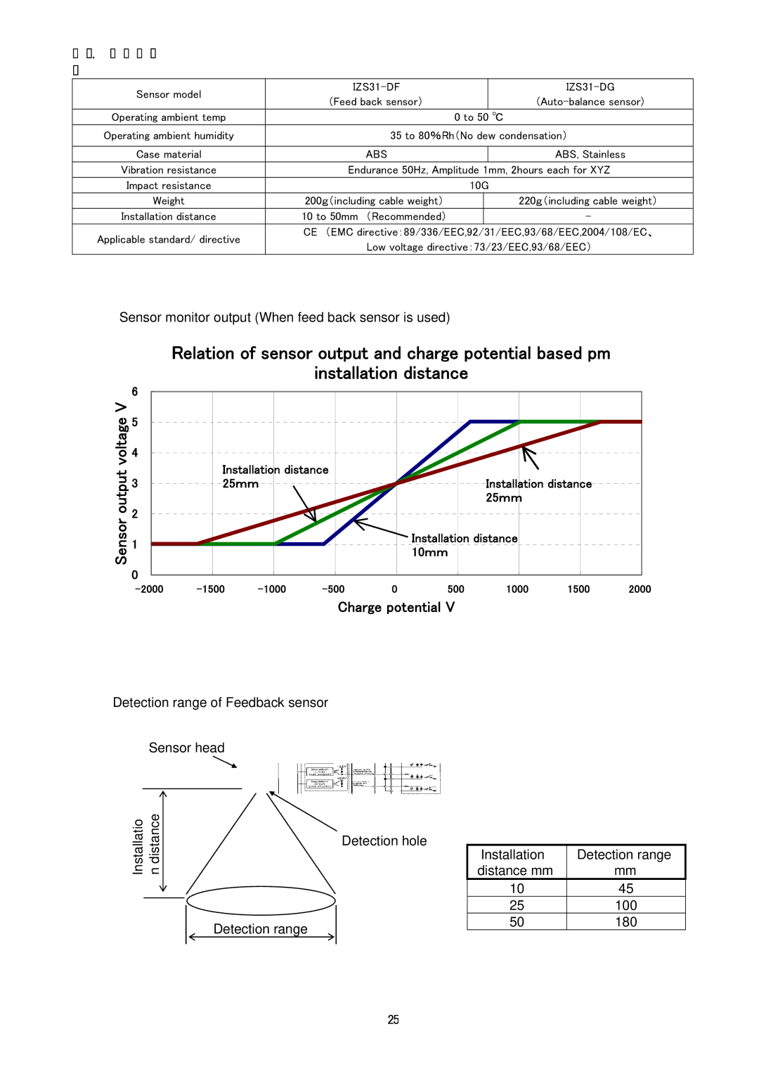
※2:When the potential of the charged object is measured with the feed back sensor, the relation between the charged potential and the
[Electrode cartridge quantity and weight]
Bar length mm | 300 | 380 | 620 | 780 | 1100 | 1260 | 1500 | 1900 | 2300 |
Q’ty of electrode | 3 | 4 | 7 | 9 | 13 | 15 | 18 | 23 | 28 |
cartridge |
|
|
|
|
|
|
|
|
|
Weight g | 330 | 400 | 600 | 720 | 1000 | 1100 | 1500 | 2000 | 2500 |
24


![Sierra Monitor Corporation IZS31 operation manual .Specifications, .Ionizer, [Electrode cartridge quantity and weight]](/prints/sierra-monitor-corporation-izs31/1052224/25.1080/specifications-ionizer.1080.webp)
