Ariston 47-116-15 installation instructions Electrical Diagram

Page 13

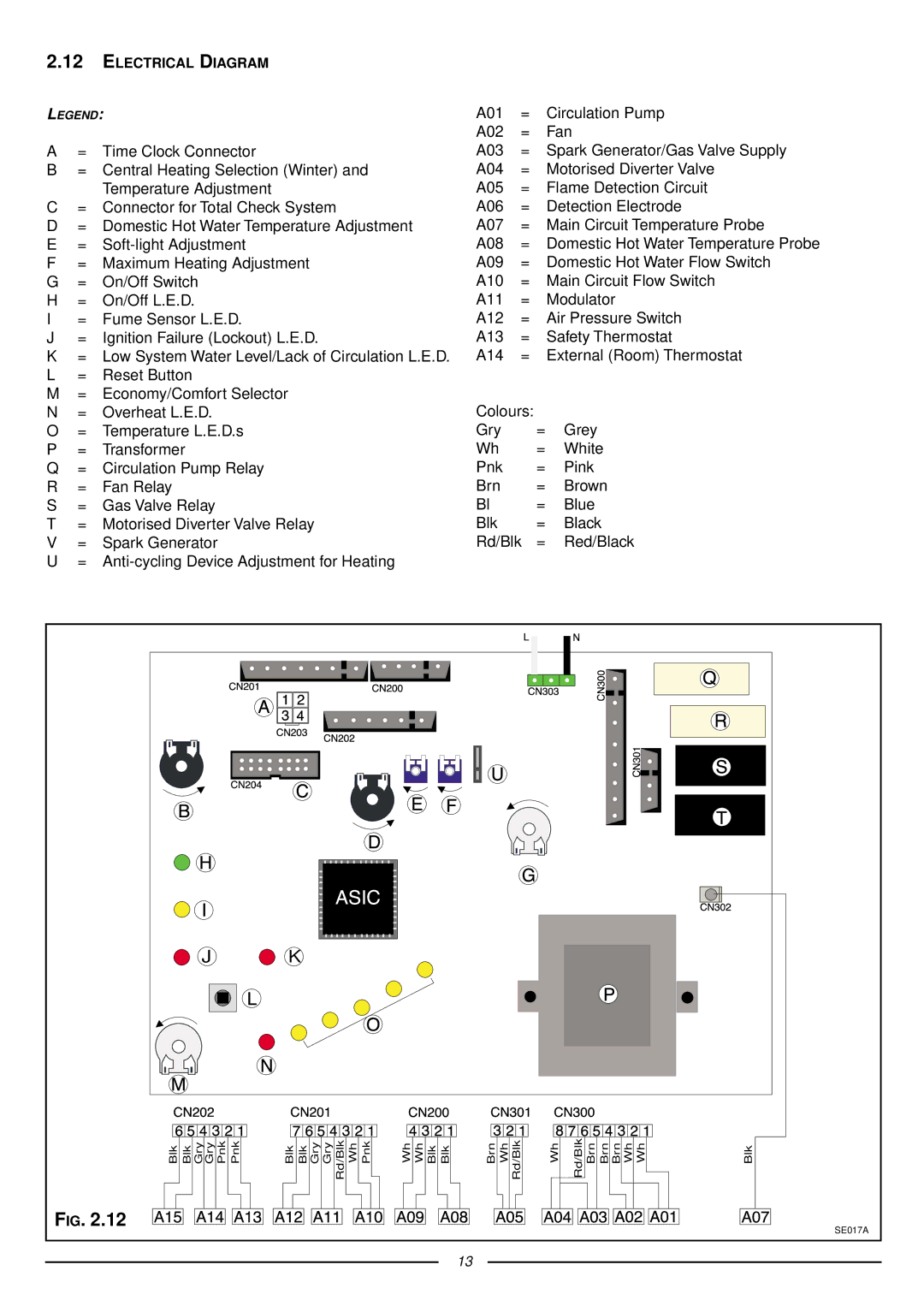
2.12ELECTRICAL DIAGRAM

LEGEND:

A01

=

Circulation Pump


A02

=

Fan

A

=

Time Clock Connector

A03

=

Spark Generator/Gas Valve Supply

B

= Central Heating Selection (Winter) and

A04

=

Motorised Diverter Valve


Temperature Adjustment

A05

=

Flame Detection Circuit

C

= Connector for Total Check System

A06

=

Detection Electrode

D

= Domestic Hot Water Temperature Adjustment

A07

=

Main Circuit Temperature Probe

E

=

Soft-light Adjustment

A08

= Domestic Hot Water Temperature Probe

F

=

Maximum Heating Adjustment

A09

= Domestic Hot Water Flow Switch

G

=

On/Off Switch

A10

= Main Circuit Flow Switch

H

=

On/Off L.E.D.

A11

=

Modulator

I

=

Fume Sensor L.E.D.

A12

=

Air Pressure Switch

J

= Ignition Failure (Lockout) L.E.D.

A13

=

Safety Thermostat

K

= Low System Water Level/Lack of Circulation L.E.D.

A14

=

External (Room) Thermostat

L= Reset Button

M= Economy/Comfort Selector

N

=

Overheat L.E.D.

Colours:


O

=

Temperature L.E.D.s

Gry

=

Grey

P

=

Transformer

Wh

=

White

Q

=

Circulation Pump Relay

Pnk

=

Pink

R

=

Fan Relay

Brn

=

Brown

S

=

Gas Valve Relay

Bl

=

Blue

T

=

Motorised Diverter Valve Relay

Blk

=

Black

V

=

Spark Generator

Rd/Blk

=

Red/Black

U

= Anti-cycling Device Adjustment for Heating


J


K


Blk

Blk Gry Gry Pnk

Pnk

Blk Blk Gry Gry

Rd/Blk Wh

Pnk

Wh Wh Blk

Blk

Brn

Wh Rd/Blk

Wh

Rd/Blk Brn

Brn Brn Wh Wh

Blk

FIG. 2.12


SE017A


13


Image 13
Contents Installation Instructions Type C Boilers Table of Contents General Information Overall View Installation Overall Dimensions Supply must be fused at 3 a Domestic Water Tonbridge Morley RoadKent TN9 1RA 80 mm Systems Restrictor Extension Piping not insulated Piping insulatedRestrictor No Restrictor Extension Piping not insulated Piping insulatedCalculating the lengths of the pipes, Electrical Diagram Central Heating Return Commissioning Control Panel Initial START-UP Operational Adjustments Status ANTI-FROST Device Methane Liquid Gas Butane GAS AdjustmentsG20 Gas G30 16.0Maintenance Boiler MiscellaneousProgrammer Technical Information Technical Service Hot Line 01494Manufacturer Merloni TermoSanitari SpA Italy Servicing Instructions Type C Boilers Fault Finding Removing the front panel Servicing InstructionsRemoving the side panels Removing the sealed chamber frontal coverRemoving the burner and jets Removing the combustion coverRemoving the electrodes Removing the main heat exchanger Removing the fan Removing the air pressure switchSetting the minimum and the maximum power of the boiler Setting the gas pressuresSetting the maximum heating circuit power Setting pressure for soft ignitionRegulating the heating power for Butane gas G30 Regulating the heating power for Natural gas G20Regulating the heating power for Propane gas G31 Removing the spark generator Removing the D.H.W. secondary exchanger Removing the gas valveRemoving the main circuit flow switch Removing the safety valveRemoving the automatic air vent Removing the pump Removing the expansion vessel Removing the pressure gaugeRemoving the heating temperature sensor N.T.C Removing the D.H.W. temperature sensor N.T.CRemoving the D.H.W. flow switch Removing the overheat thermostatRemoving the time clock Checking the fusesRemoving the P.C.B Finding diagrams described in this chapter Fault FindingYES YES ∆ P 1.2 mbar YES Electrical Diagrams MicroGENUS 23/27 Mffi MicroGENUS 23/27 Mffi Ariston Page Manufacturer Merloni TermoSanitari SpA Italy Microgenus 27 Mffi Cod Part Code Description 998924 Panel combustion chamber front 571770 Main flow switch top cap