2.INSTALLATION
2.1REFERENCE STANDARDS
2.2 SITING THE APPLIANCE
The technical information and instructions provided herein below are intended for the installer so that the unit may be installed correctly and safely.
The installation and initial start up of the boiler must be by a CORGI Approved Installer in compliance with the installation standards currently in effect, as well as with any and all local health and safety standards i.e..
CORGI .
This appliance must be installed by a competent installer in accordance with current Gas Safety (installation & use) Regulations.
The installation of this appliance must be in accordance with the relevant requirements of the current Gas Safety (installation & use) Regulations, the Local Building Regulations, the current I.E.E. Wiring Regulations, the byelaws of the local water authority, and in Scotland, in accordance with the Building Standards (Scotland) Regulation and Health and Safety document No. 635 “Electricity at work regs. 1989”.
Installation should also comply with the following British Standard Codes of Practice:
Low pressure |
|
|
pipes | BS 6891 | 1988 |
|
|
|
Boilers of rated input |
|
|
not exceeding 60 kW | BS 6798 | 1987 |
|
|
|
Forced circulation hot |
|
|
water system | BS 5449 | 1990 |
|
|
|
Installation of gas hot water |
|
|
supplies for domestic purposes |
|
|
( 2nd family gases) | BS 5546 | 1990 |
Flues | BS | 1990 |
|
|
|
Air supply | BS | 1989 |
|
|
|
The appliance may be installed in any room or indoor area, although particular attention is drawn to the requirements of the current I.E.E. Wiring Regulations, and in Scotland, the electrical provisions of the Building Regulations applicable in Scotland, with respect to the installation of the combined appliance in a room containing a bath or shower.
Where a
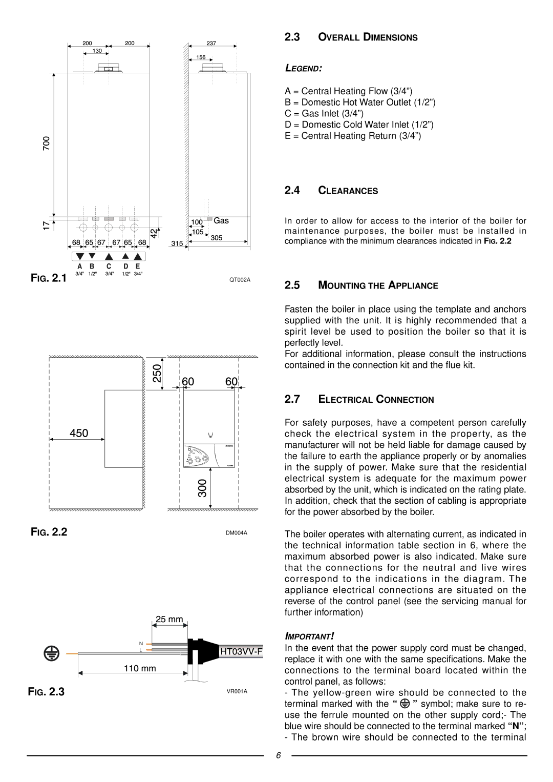
The location must permit adequate space for servicing and air circulation around the appliance as indicated in paragraph 2.4.
The location must permit the provision of an adequate flue and termination. For unusual locations special procedures may be necessary.
BS
A compartment used to enclose the appliance must be designed specifically for this purpose. No specific ventilation requirements are needed for the installation within a cupboard.
This appliance is not suitable for outdoor installation.
The type C appliances (in which the combustion circuit, air vent intake and combustion chamber are
There are no limitations with respect to ventilation and the volume of the room itself. The boiler must be installed on a solid, permanent wall to prevent access to the electrical parts (when live) through the aperture on the back frame.
5
