1.GENERAL INFORMATION
1.1GENERAL INSTRUCTIONS
This manual is an integral and essential part of the product. It should be kept with the appliance so that it can be consulted by the user and our authorised personnel.
Please carefully read the instructions and notices about the unit contained in this manual, as they provide important information regarding the safe installation, use and maintenance of the product.
For operating instructions please consult the separate User’s Manual.
CO034A
Read the instructions and recommendations in these Installation Instructions carefully to ensure proper installation, use and maintenance of the appliance.
Keep this manual in a safe place. You may need it for your own reference while our Servicing Centre technicians or your installer may need to consult it in the future.
This is a combined appliance for the production of central heating (C.H.) and domestic hot water (D.H.W.).
This appliance must be used only for the purpose for which it is designed.
The manufacturer declines all liability for damage caused by improper or negligent use.
No asbestos or other hazardous materials have been used in the fabrication of this product.
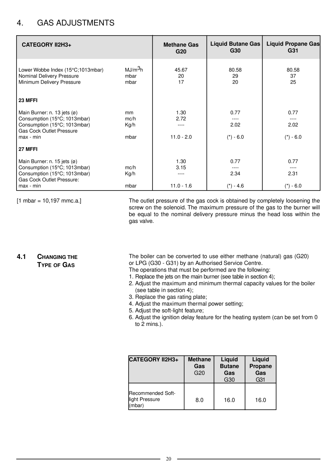
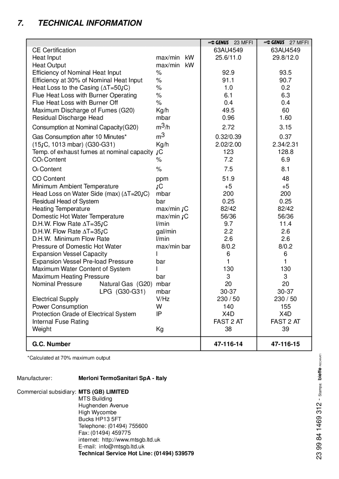
Before connecting the appliance, check that the information shown on the data plate and the table on pages
The gas with which this appliance operates is also shown on the label at the bottom of the boiler.
Do not install this appliance in a damp environment or close to equipment which spray water or other liquids.
Do not place objects on the appliance.
Do not allow children or inexperienced persons to use the appliance without supervision.
If you smell gas in the room, do not turn on light switches, use the telephone or any other object which might cause sparks.
Open doors and windows immediately to ventilate the room.
Shut the gas mains tap (on the gas meter) or the valve of the gas cylinder and call your Gas Supplier immediately.
If you are going away for a long period of time, remember to shut the mains gas tap or the gas cylinder valve.
Always disconnect the appliance either by unplugging it from the mains or turning off the mains switch before cleaning the appliance or carrying out maintenance.
In the case of faults or failure, switch off the appliance and turn off the gas tap. Do not tamper with the appliance.
For repairs, call your local Authorised Servicing Centre and request the use of original spare parts. For
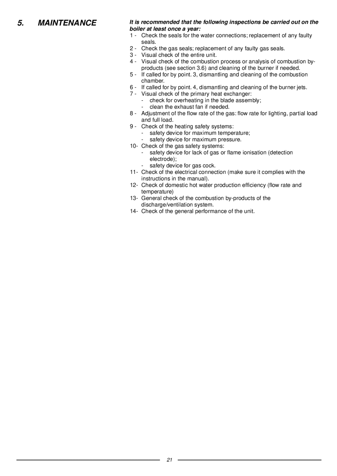
Check the following at least once a year:
1 - Check the seals for the water connections; replacement of any faulty seals. 2 - Check the gas seals; replacement of any faulty gas seals.
3 - Visual check of the entire unit.
4 - Visual check of the combustion process or analysis of combustion by- products (see section 3.6) and cleaning of the burner if needed.
3
