Ariston 47-116-15 installation instructions Domestic Water

Page 8

PIPE WORK:

Copper tubing to BS EN 1057:1996 is recommended for water pipes. Jointing should be either with capillary soldered or compression fittings. Where possible pipes should have a gradient to ensure air is carried naturally to air release points and water flows naturally to drain taps.

The appliance has a built-in automatic air release valve, however it should be ensured as far as possible that the appliance heat exchanger is not a natural collecting point for air.

Except where providing useful heat, pipes should be insulated to prevent heat loss and avoid freezing.

Particular attention should be paid to pipes passing through ventilated spaces in roofs and under floors.

BY-PASS:

The appliance includes an automatic by-pass valve, which protects the main heat exchanger in case of reduced or interrupted water circulation through the heating system, due to the closing of thermostatic valves or cock-type valves within the system.

SYSTEM DESIGN:

This boiler is suitable only for sealed systems. Drain Cocks:

These must be located in accessible positions to permit the draining of the whole system. The taps must be at least 15mm nominal size and manufactured in accordance with BS 2870:1980.

SAFETY VALVE DISCHARGE:

The discharge should terminate facing downward on the exterior of the building in a position where discharging (possibly boiling water & steam) will not create danger or nuisance, but in an easily visible position, and not cause damage to electrical components and wiring.

The discharge must not be over an entrance or a window or any other type of public access.

AIR RELEASE POINTS:

These must be fitted at all high points where air naturally collects and must be sited to facilitate complete filling of the system.

The appliance has an integral sealed expansion vessel to accommodate the increase of water value when the system is heated.

It can accept up to 6 l (1.3 gal) of expansion water. If the heating circuit has an unusually high water content, calculate the total expansion and add an additional sealed expansion vessel with adequate capacity.

MAINS WATER FEED - CENTRAL HEATING:

There must be no direct connection to the mains water supply even through a non-return valve, without the approval of the Local Water Authority.

FILLING:

A temporary method for initially filling the system and replacing lost water during servicing in accordance with Water Supply Byelaw 14 must be provided.

DOMESTIC WATER

The domestic water must be in accordance with the relevant recommendation of BS 5546:1990. Copper tubing to BS EN 1057:1996 is recommended for water carrying pipe work and must be used for pipe work carrying drinking water.

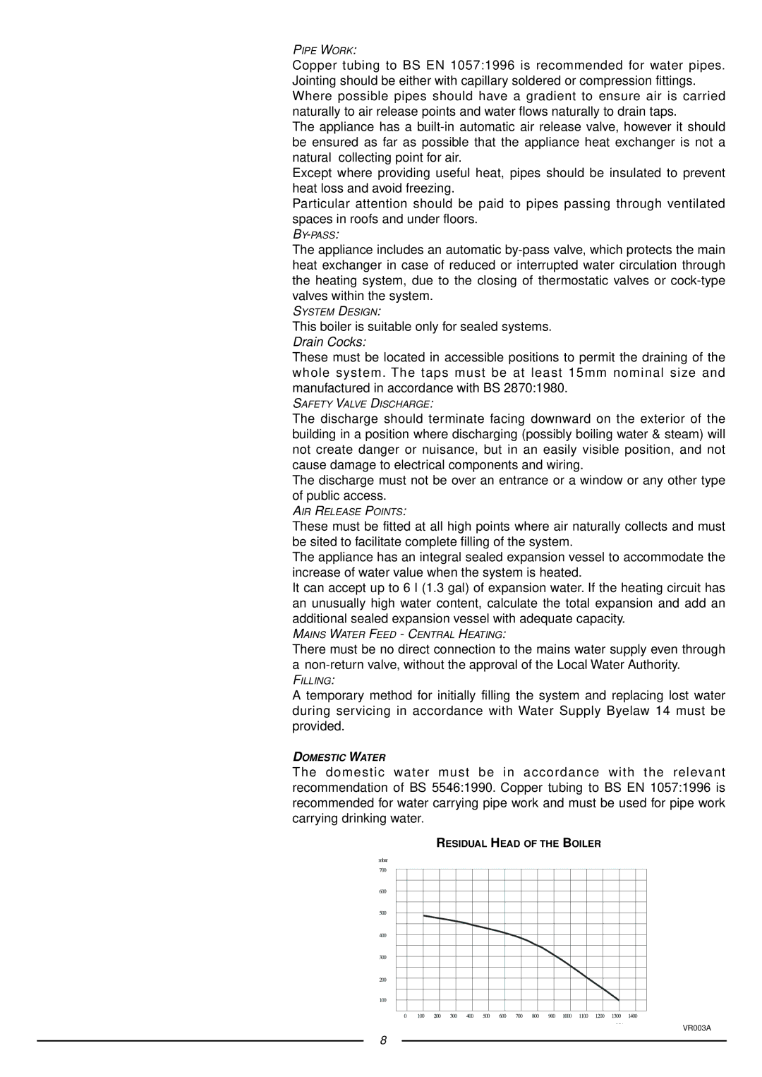
RESIDUAL HEAD OF THE BOILER

VR003A

8
Image 8
Contents Installation Instructions Type C Boilers Table of Contents General Information Overall View Installation Overall Dimensions Supply must be fused at 3 a Domestic Water Kent TN9 1RA Morley RoadTonbridge 80 mm Restrictor Extension Piping not insulated Piping insulated SystemsRestrictor No Restrictor Extension Piping not insulated Piping insulatedCalculating the lengths of the pipes, Electrical Diagram Central Heating Return Commissioning Control Panel Initial START-UP Operational Adjustments Status ANTI-FROST Device GAS Adjustments Methane Liquid Gas ButaneG20 Gas G30 16.0Maintenance Miscellaneous BoilerProgrammer Manufacturer Merloni TermoSanitari SpA Italy Technical Service Hot Line 01494Technical Information Servicing Instructions Type C Boilers Fault Finding Servicing Instructions Removing the front panelRemoving the sealed chamber frontal cover Removing the side panelsRemoving the electrodes Removing the combustion coverRemoving the burner and jets Removing the main heat exchanger Removing the air pressure switch Removing the fanSetting the gas pressures Setting the minimum and the maximum power of the boilerSetting the maximum heating circuit power Setting pressure for soft ignitionRegulating the heating power for Propane gas G31 Regulating the heating power for Natural gas G20Regulating the heating power for Butane gas G30 Removing the spark generator Removing the gas valve Removing the D.H.W. secondary exchangerRemoving the automatic air vent Removing the safety valveRemoving the main circuit flow switch Removing the pump Removing the pressure gauge Removing the expansion vesselRemoving the D.H.W. temperature sensor N.T.C Removing the heating temperature sensor N.T.CRemoving the D.H.W. flow switch Removing the overheat thermostatChecking the fuses Removing the time clockRemoving the P.C.B Fault Finding Finding diagrams described in this chapterYES YES ∆ P 1.2 mbar YES Electrical Diagrams MicroGENUS 23/27 Mffi MicroGENUS 23/27 Mffi Ariston Page Manufacturer Merloni TermoSanitari SpA Italy Microgenus 27 Mffi Cod Part Code Description 998924 Panel combustion chamber front 571770 Main flow switch top cap