Ariston 47-116-15 installation instructions Morley Road, Tonbridge, Kent TN9 1RA

Page 9

2.9 FLUE CONNECTIONS

FLUE SYSTEM


The provision for satisfactory flue termination must be made as described


in BS 5440-1.


The appliance must be installed so that the flue terminal is exposed to outdoor air.


The terminal must not discharge into another room or space such as an


outhouse or lean-to.


It is important that the position of the terminal allows a free passage of air


across it at all times.


The terminal should be located with due regard for the damage or


discolouration that might occur on buildings in the vicinity.


In cold or humid weather water vapour may condense on leaving the flue


terminal.


The effect of such “steaming” must be considered.


If the terminal is less than 2 metres above a balcony, above ground or above


a flat roof to which people have access, then a suitable terminal guard must


be fitted. When ordering a terminal guard, quote the appliance model


number.


A suitable terminal guard is available from:


TOWER FLUE COMPONENTS


Morley Road


Tonbridge


Kent TN9 1RA


The minimum acceptable spacing from the terminal to obstructions and


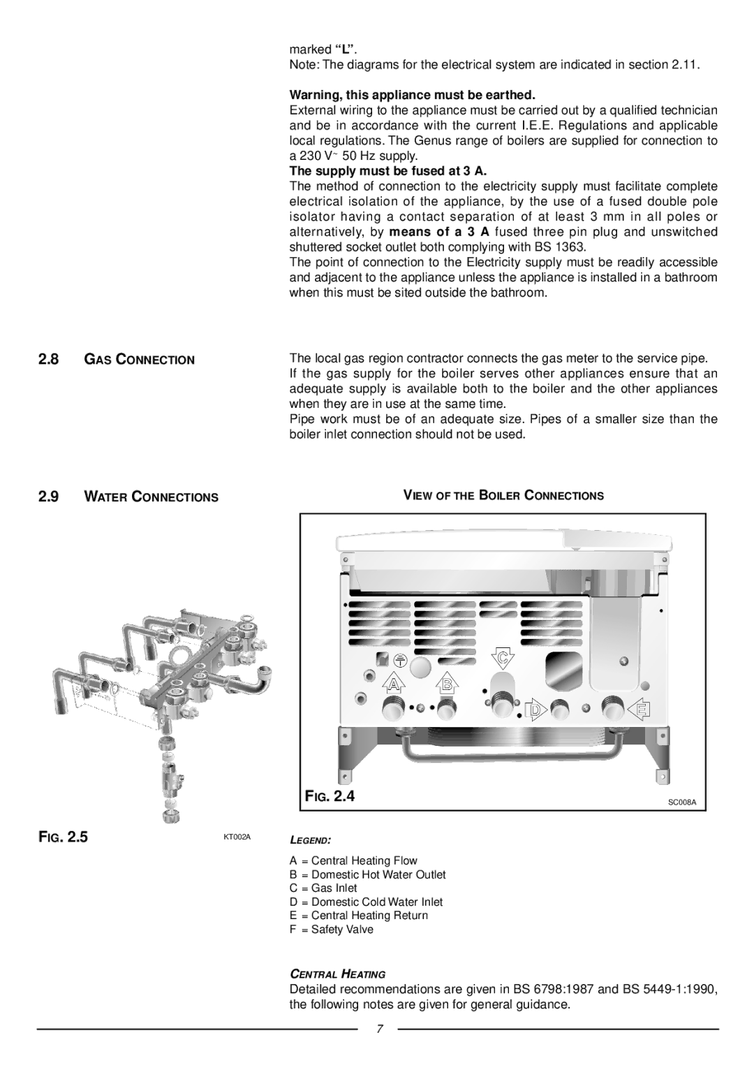
ventilation openings are specified in FIG. 2.6.

BC

F D

F

G

TERMINAL POSTION

mm

A - Directly below an open window or other opening

300

B - Below gutters, solid pipes or drain pipes

75

C - Below eaves

200

D - Below balconies or car-port roof

200

E - From vertical drain pipes and soil pipes

75

F - From internal or external corners

300

G - Above ground or below balcony level

300

HI

J

AE

L K

G

H - From a surface facing a terminal

600

I - From a terminal facing a terminal

1200

J - From an opening in the car port


(e.g. door, window) into dwelling

1200

K - Vertically from a terminal in the same wall

1500

L - Horizontally from a terminal in the same wall

300

FIG. 2.6

FU010A

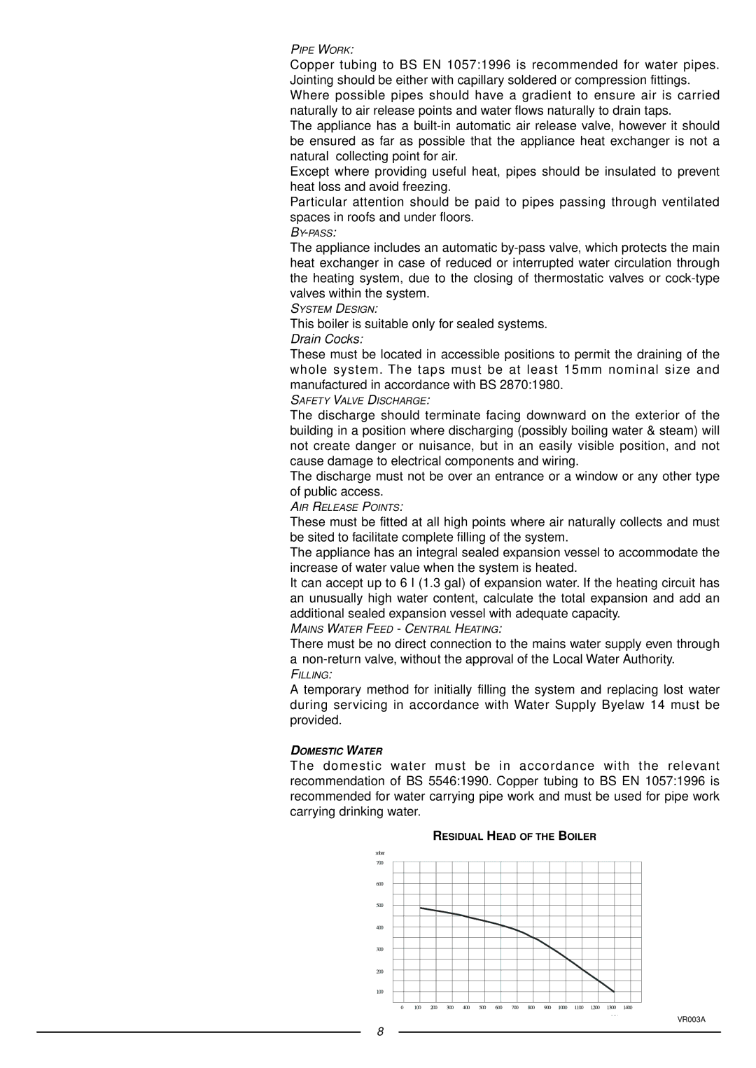
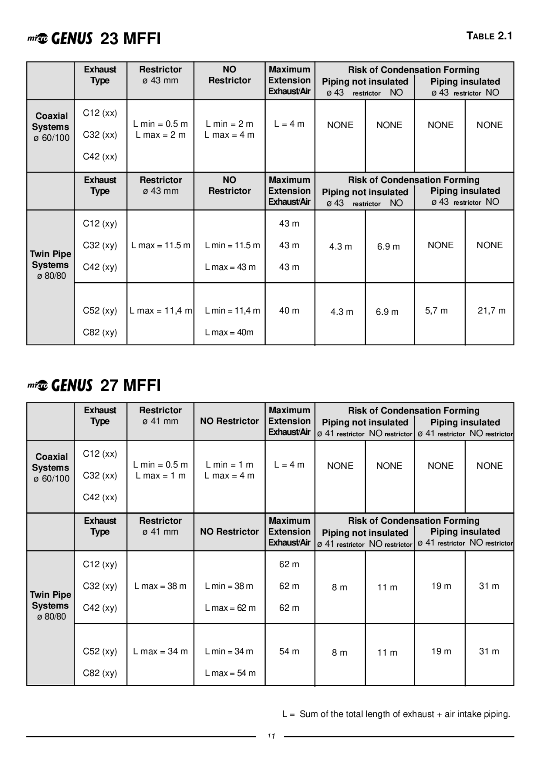
The boiler is designed to be connected to a coaxial flue discharge system.

Ø 60/100 mm

FU025A

FU002A

FIG. 2.7

9

Image 9
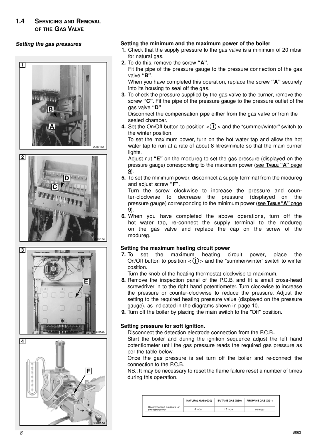
Contents Installation Instructions Type C Boilers Table of Contents General Information Overall View Installation Overall Dimensions Supply must be fused at 3 a Domestic Water Morley Road TonbridgeKent TN9 1RA 80 mm Systems Restrictor Extension Piping not insulated Piping insulatedRestrictor No Restrictor Extension Piping not insulated Piping insulatedCalculating the lengths of the pipes, Electrical Diagram Central Heating Return Commissioning Control Panel Initial START-UP Operational Adjustments Status ANTI-FROST Device Methane Liquid Gas Butane GAS AdjustmentsG20 Gas G30 16.0Maintenance Boiler MiscellaneousProgrammer Technical Service Hot Line 01494 Technical InformationManufacturer Merloni TermoSanitari SpA Italy Servicing Instructions Type C Boilers Fault Finding Removing the front panel Servicing InstructionsRemoving the side panels Removing the sealed chamber frontal coverRemoving the combustion cover Removing the burner and jetsRemoving the electrodes Removing the main heat exchanger Removing the fan Removing the air pressure switchSetting the minimum and the maximum power of the boiler Setting the gas pressuresSetting the maximum heating circuit power Setting pressure for soft ignitionRegulating the heating power for Natural gas G20 Regulating the heating power for Butane gas G30Regulating the heating power for Propane gas G31 Removing the spark generator Removing the D.H.W. secondary exchanger Removing the gas valveRemoving the safety valve Removing the main circuit flow switchRemoving the automatic air vent Removing the pump Removing the expansion vessel Removing the pressure gaugeRemoving the heating temperature sensor N.T.C Removing the D.H.W. temperature sensor N.T.CRemoving the D.H.W. flow switch Removing the overheat thermostatRemoving the time clock Checking the fusesRemoving the P.C.B Finding diagrams described in this chapter Fault FindingYES YES ∆ P 1.2 mbar YES Electrical Diagrams MicroGENUS 23/27 Mffi MicroGENUS 23/27 Mffi Ariston Page Manufacturer Merloni TermoSanitari SpA Italy Microgenus 27 Mffi Cod Part Code Description 998924 Panel combustion chamber front 571770 Main flow switch top cap