Ariston 47-116-15 installation instructions Control Panel

Page 16

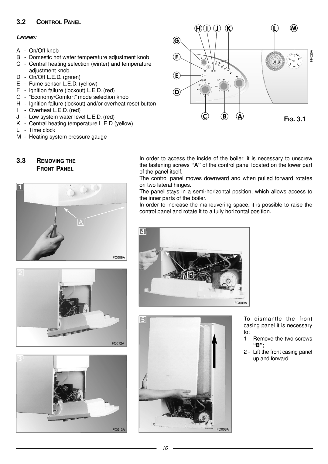
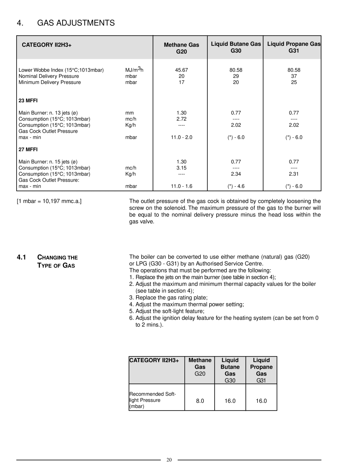
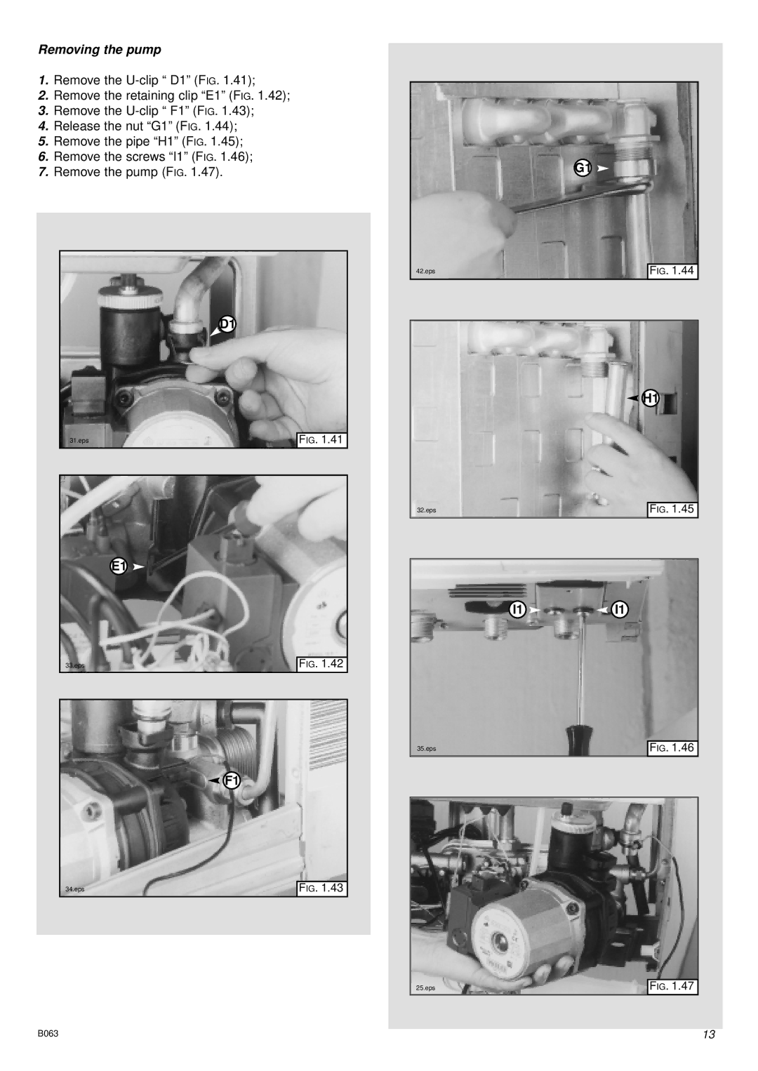
3.2CONTROL PANEL

LEGEND:

A- On/Off knob

B- Domestic hot water temperature adjustment knob

C- Central heating selection (winter) and temperature adjustment knob

D- On/Off L.E.D. (green)

E- Fume sensor L.E.D. (yellow)

F- Ignition failure (lockout) L.E.D. (red)

G- “Economy/Comfort” mode selection knob

H- Ignition failure (lockout) and/or overheat reset button

I- Overheat L.E.D. (red)

J- Low system water level L.E.D. (red)

K- Central heating temperature L.E.D (yellow)

L- Time clock

M- Heating system pressure gauge

FR025A

FIG. 3.1

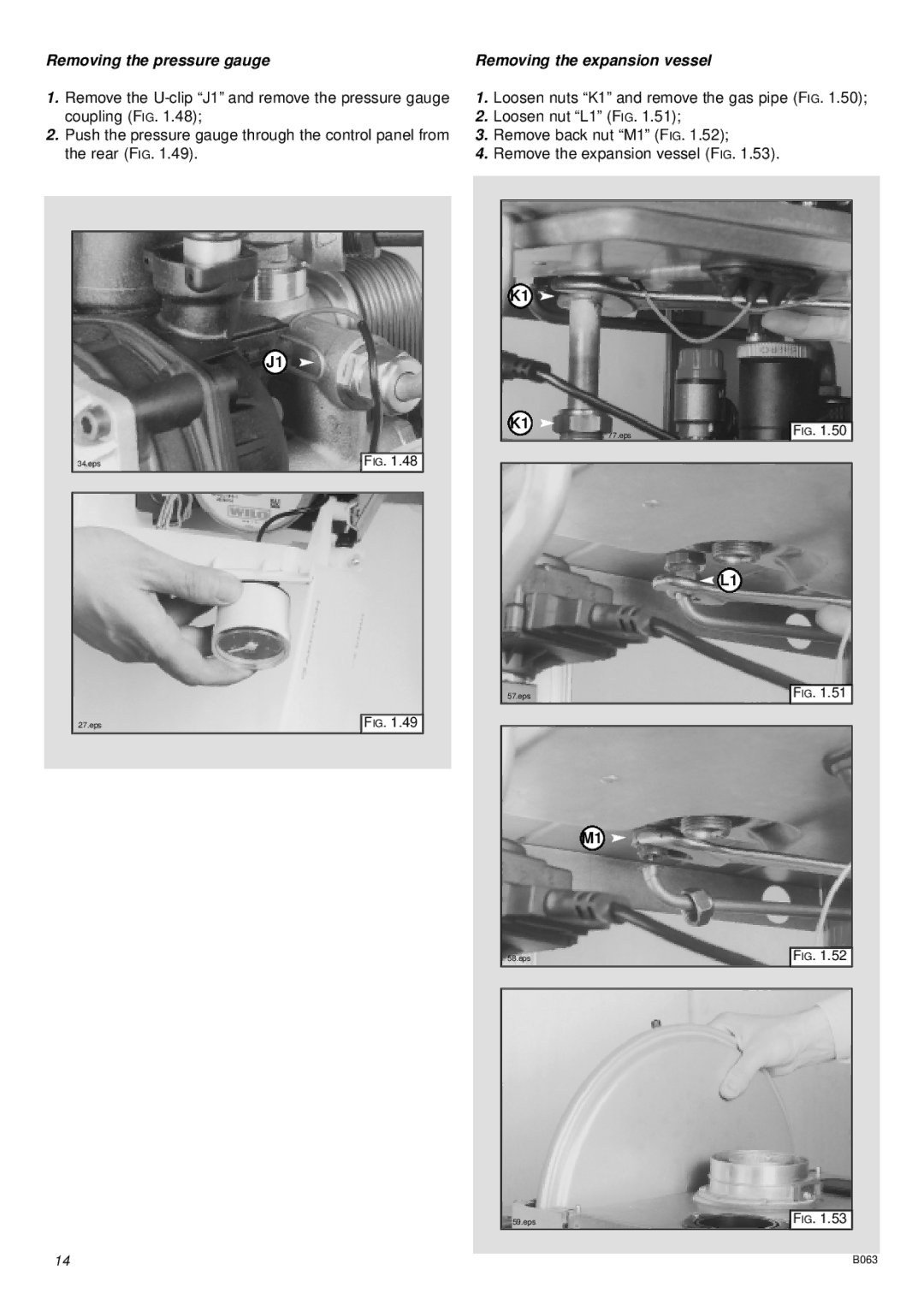
3.3REMOVING THE FRONT PANEL

1

A

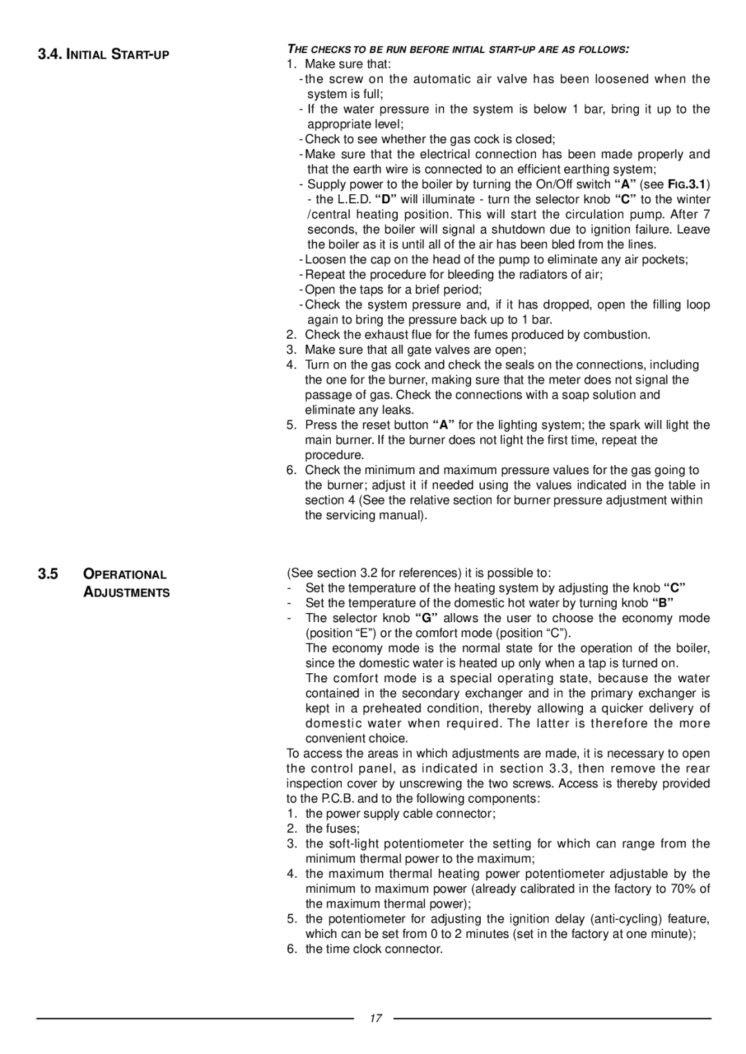
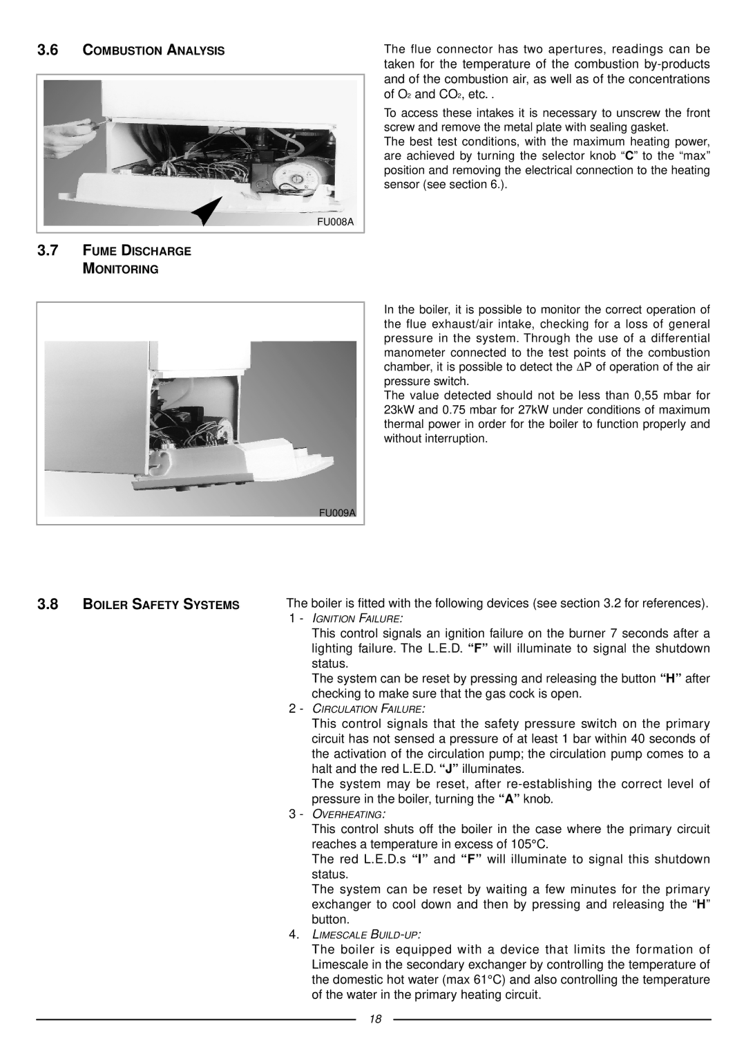
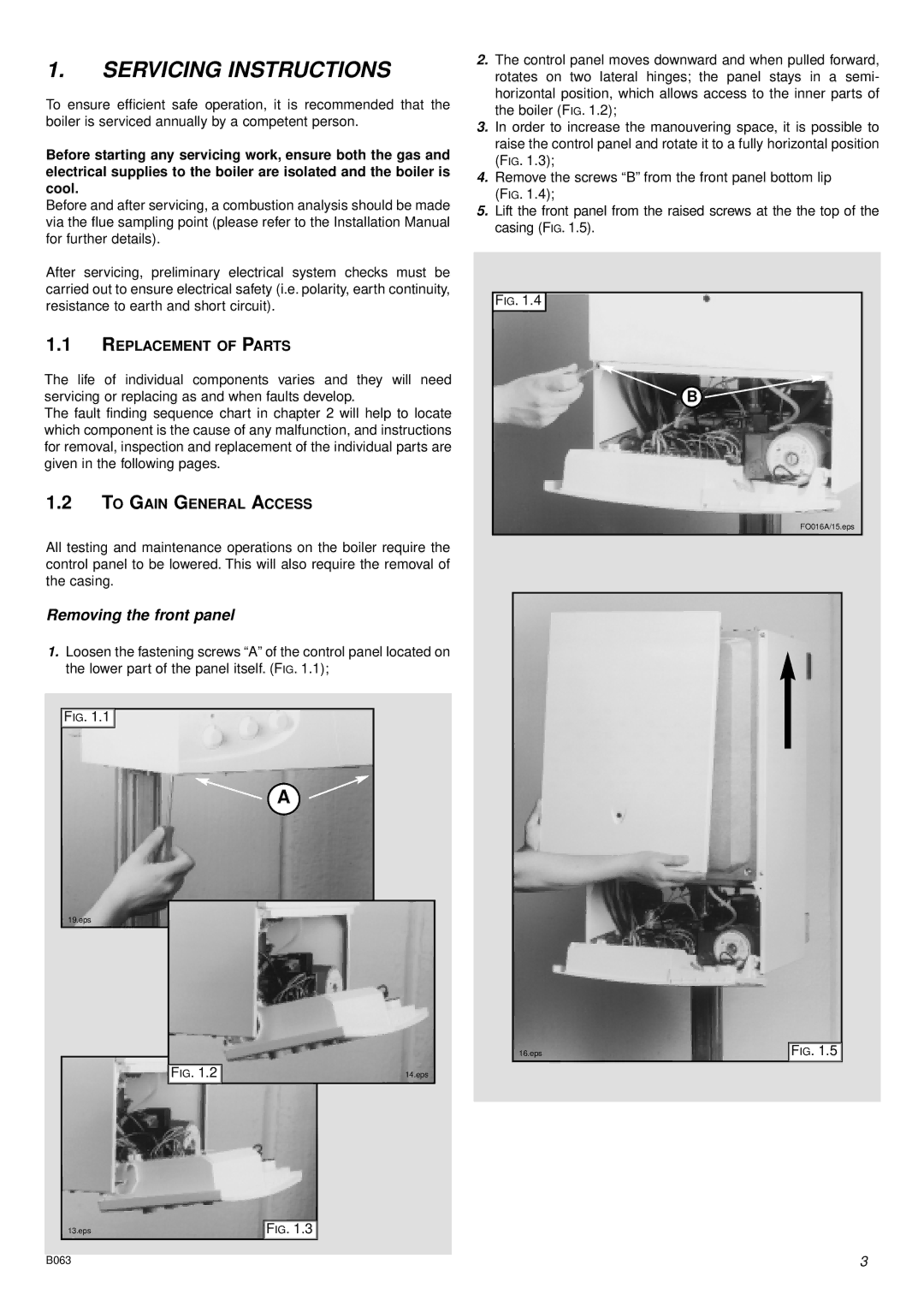
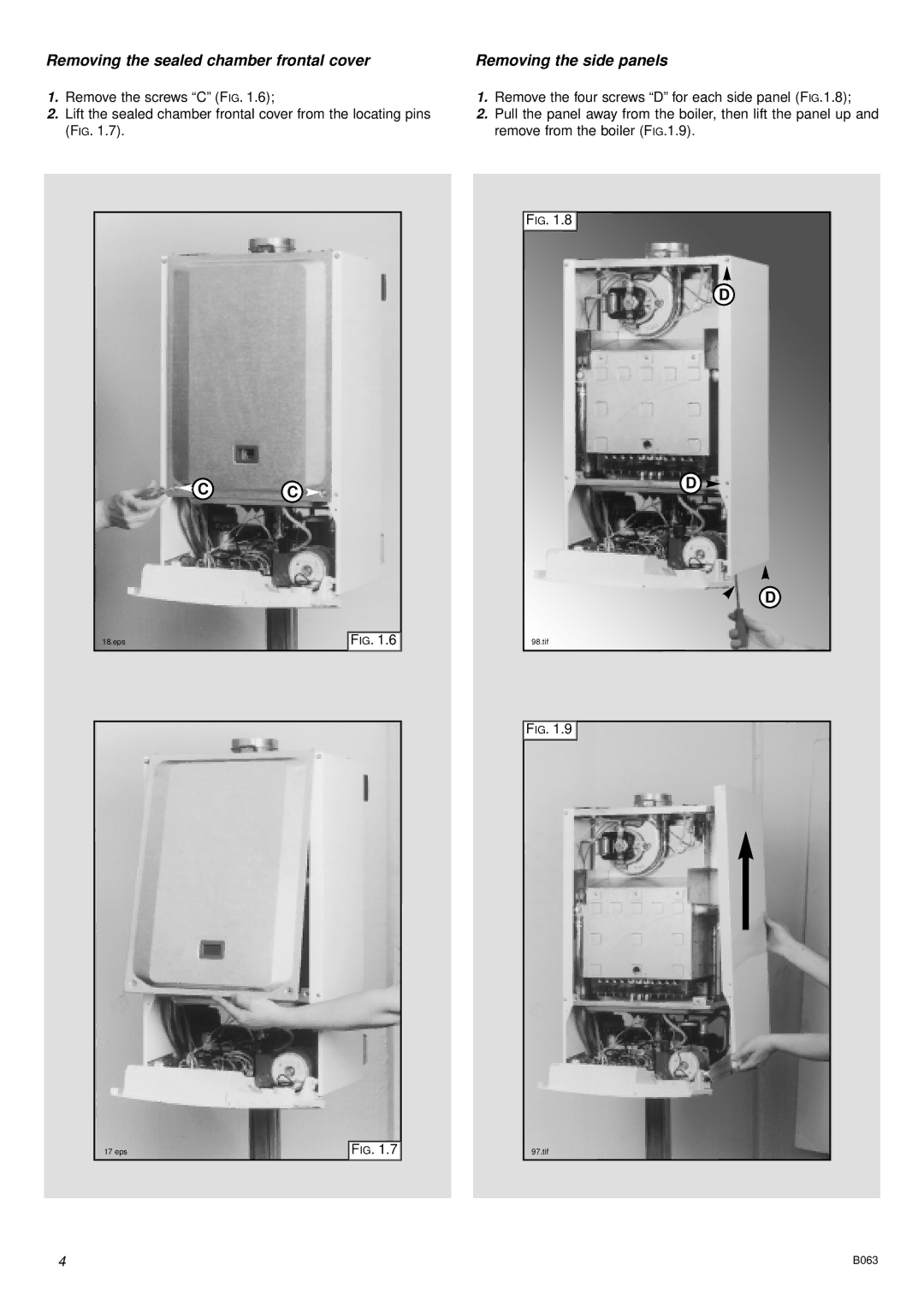
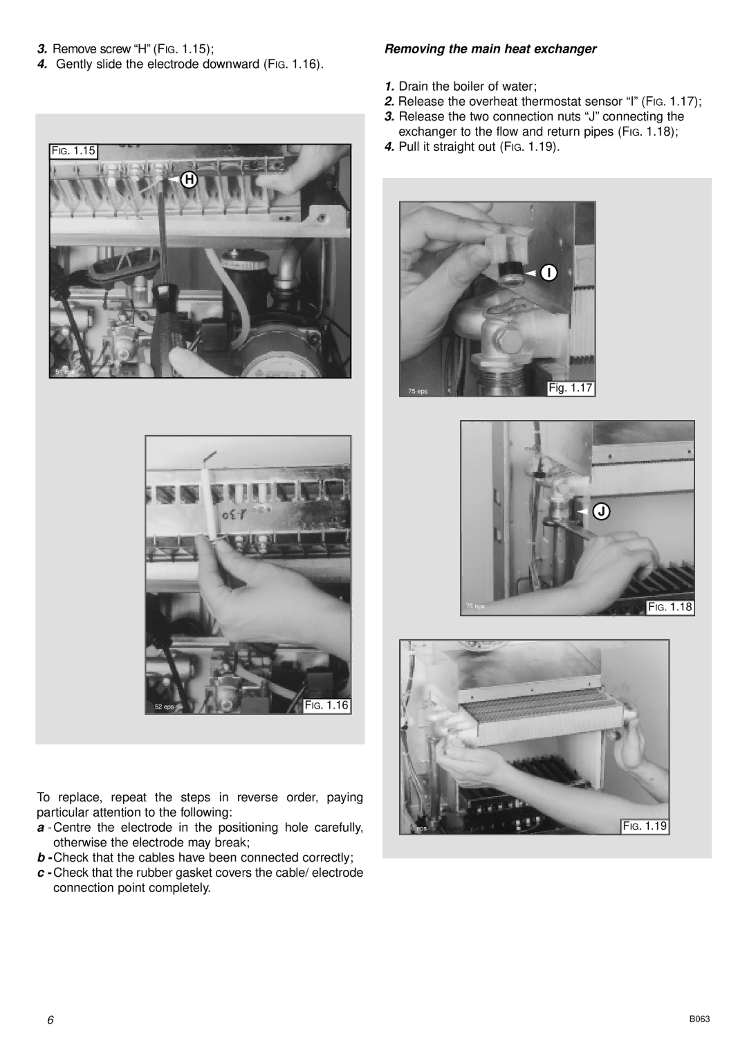
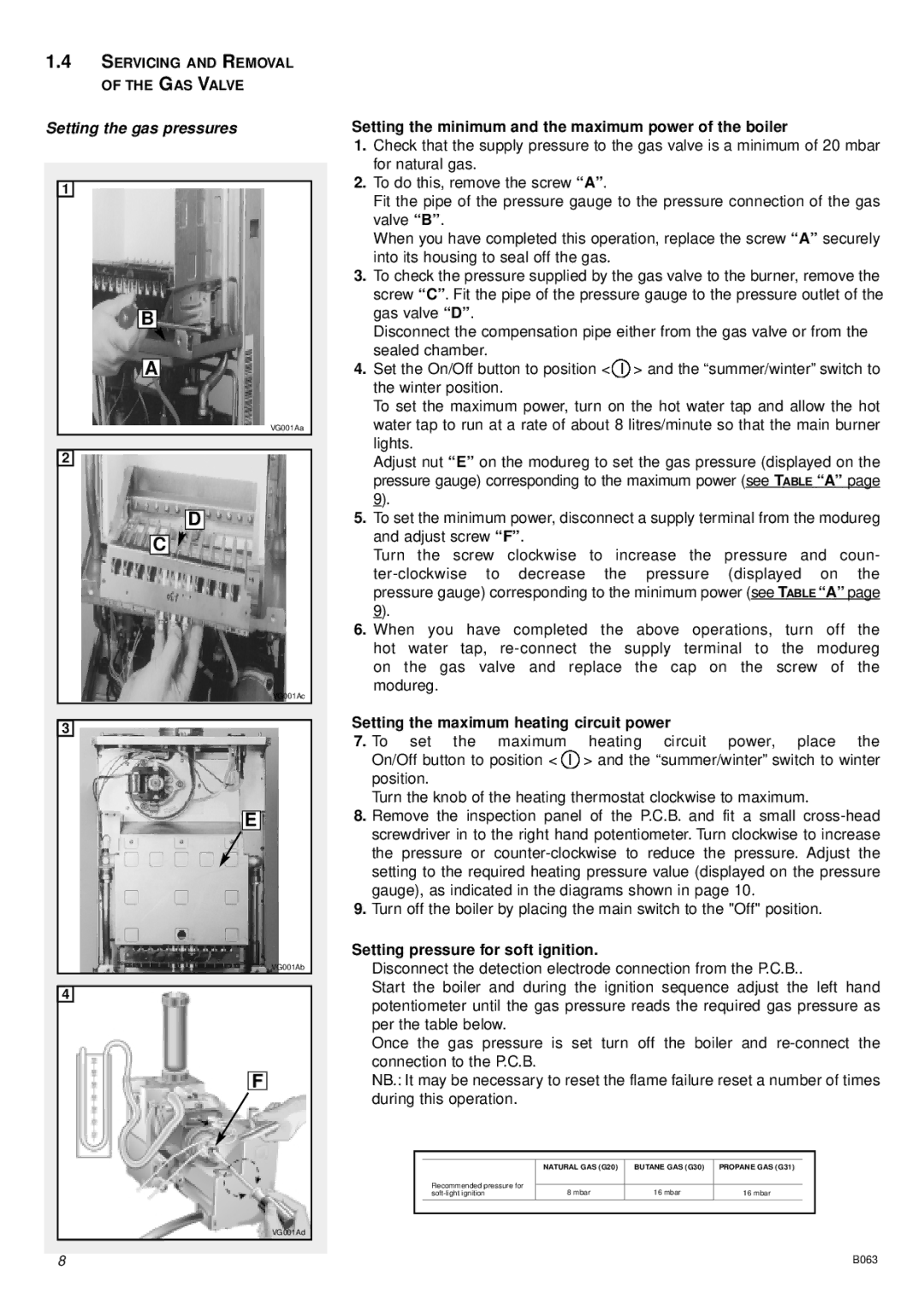
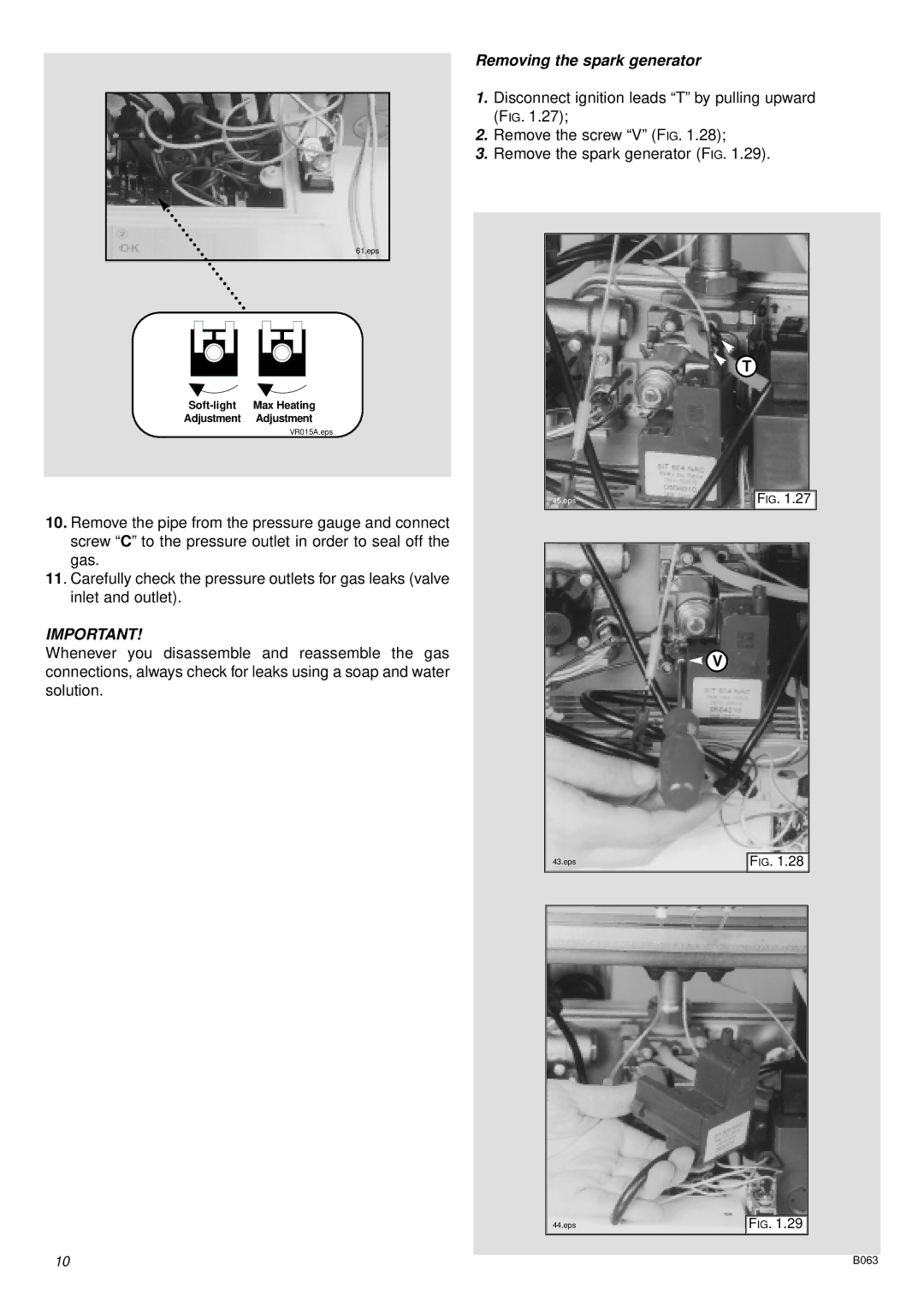
In order to access the inside of the boiler, it is necessary to unscrew the fastening screws “A” of the control panel located on the lower part of the panel itself.

The control panel moves downward and when pulled forward rotates on two lateral hinges.

The panel stays in a semi-horizontal position, which allows access to the inner parts of the boiler.

In order to increase the maneuvering space, it is possible to raise the control panel and rotate it to a fully horizontal position.

FO006A

2

FO012A

3

4

B

5

FO009A

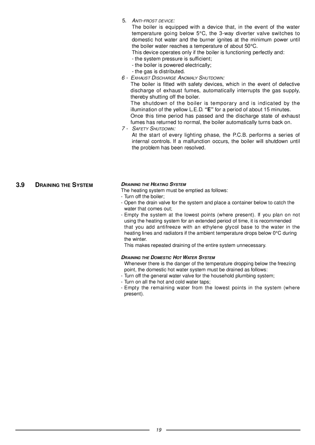
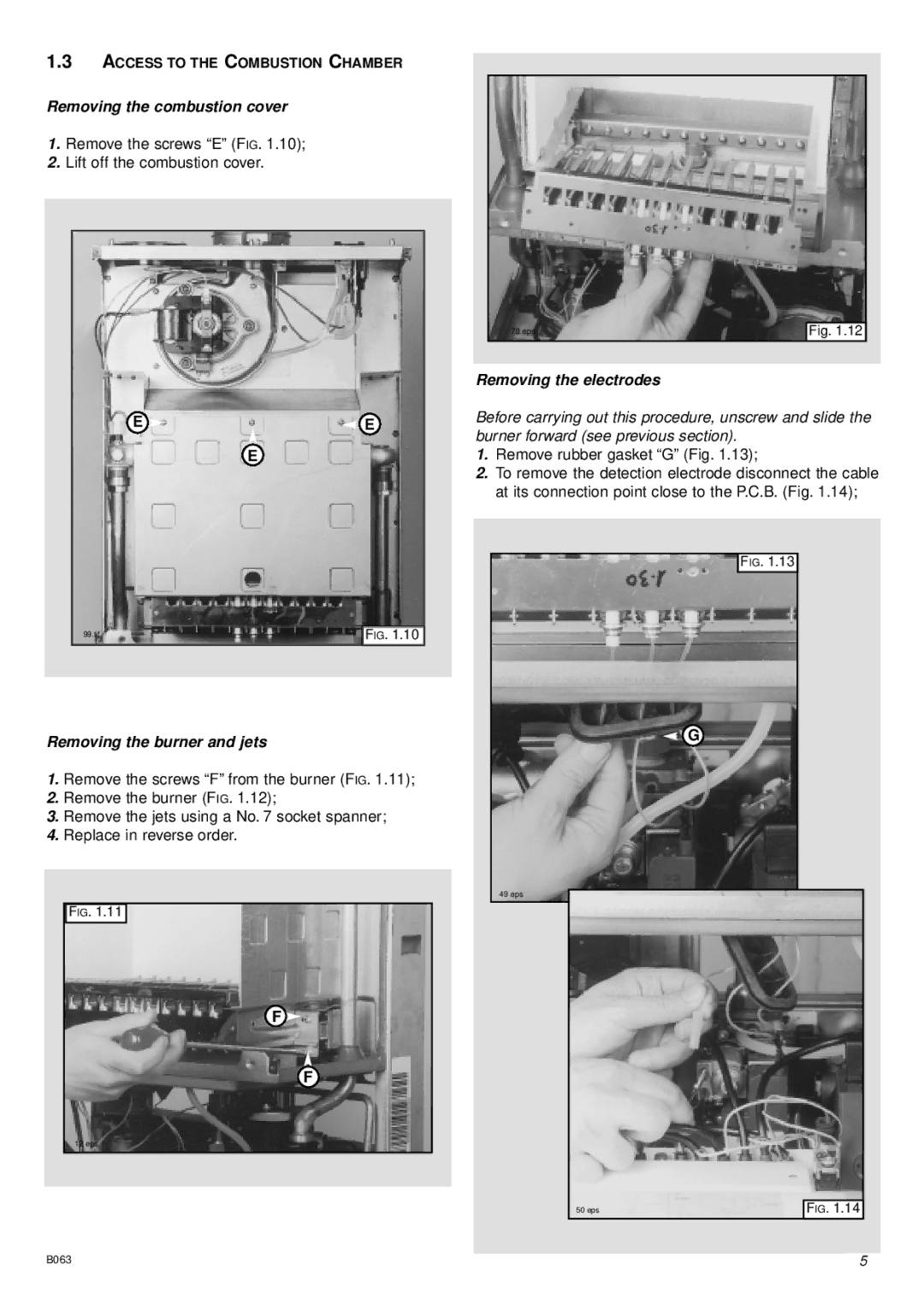
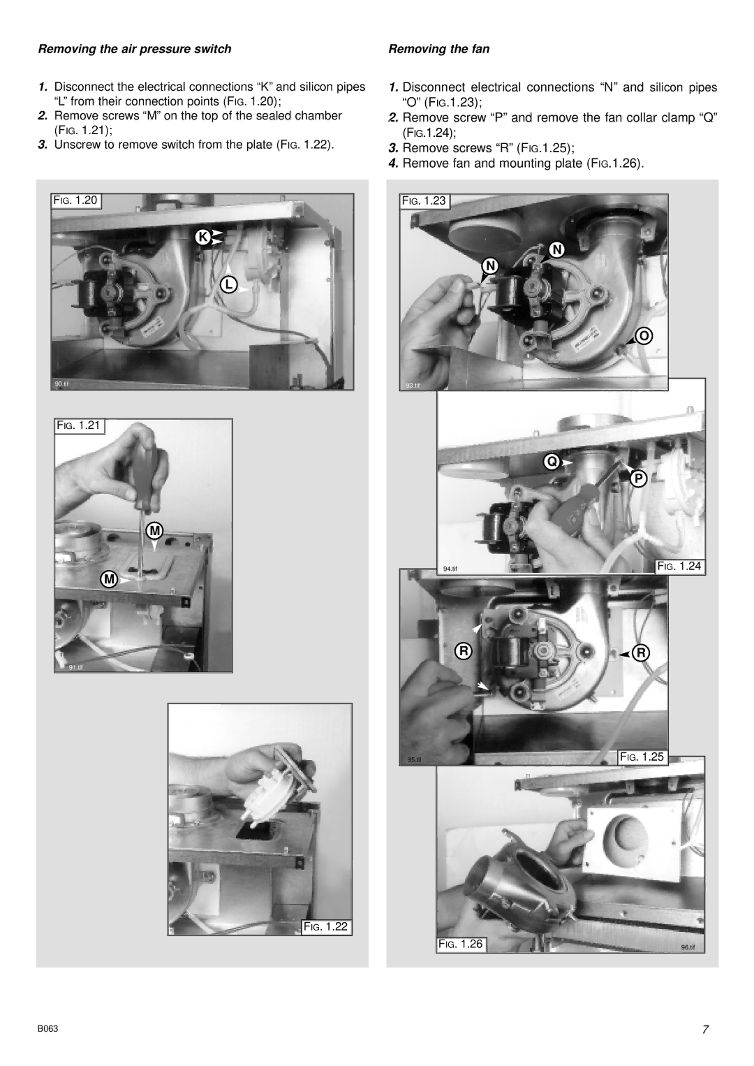
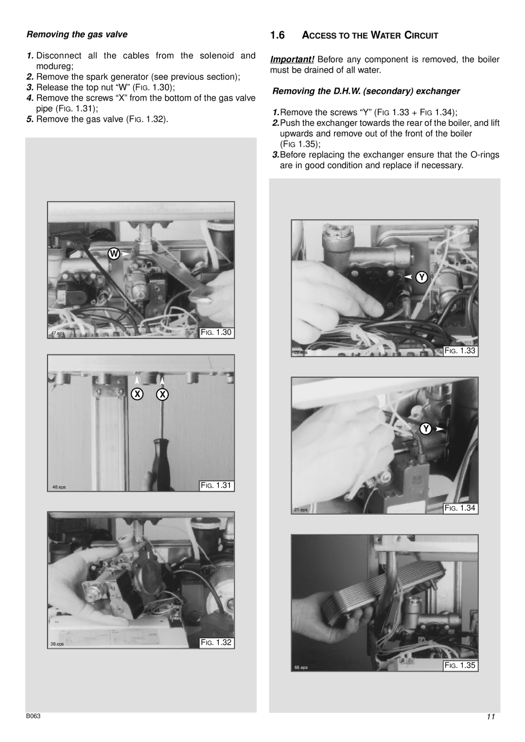
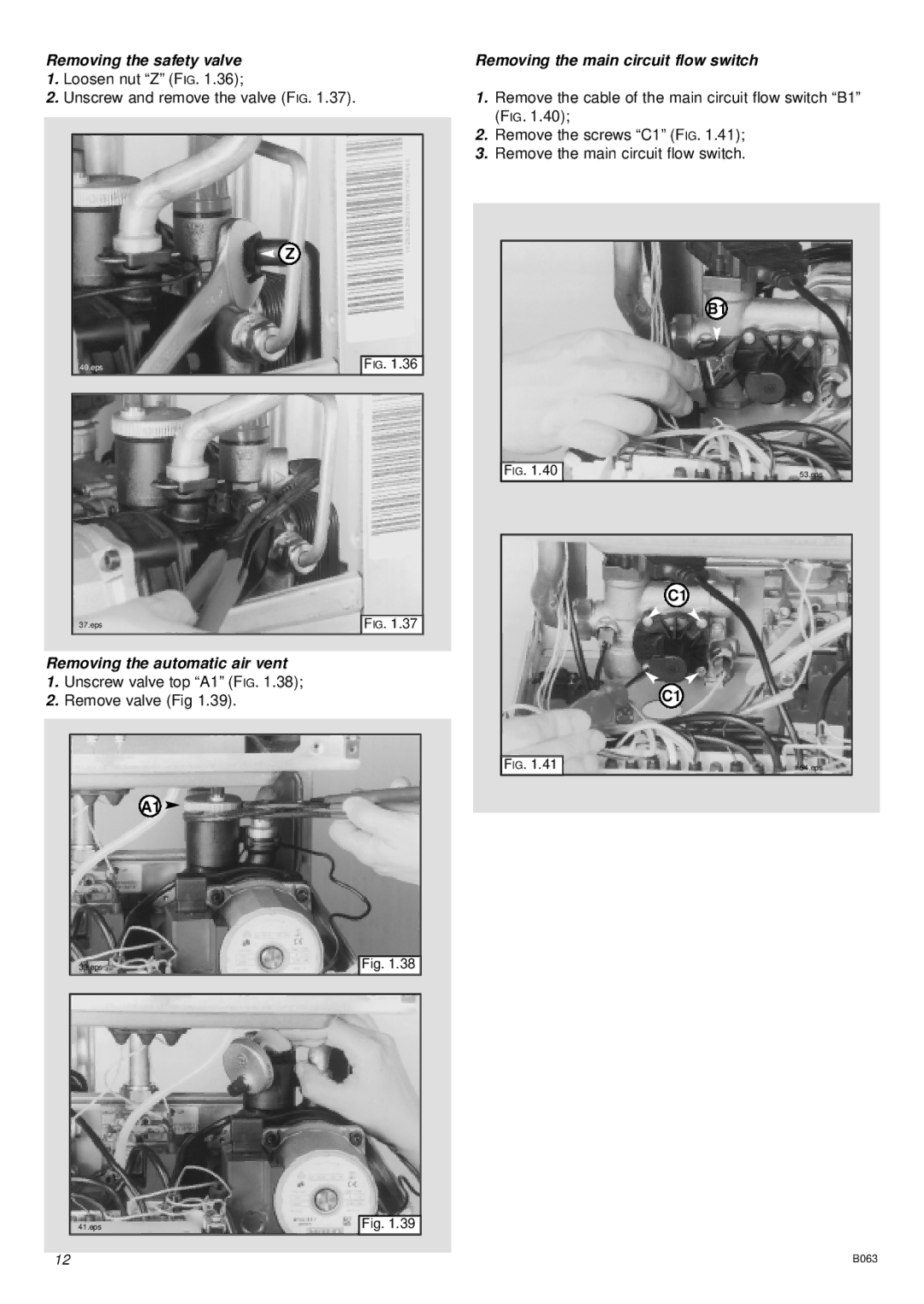
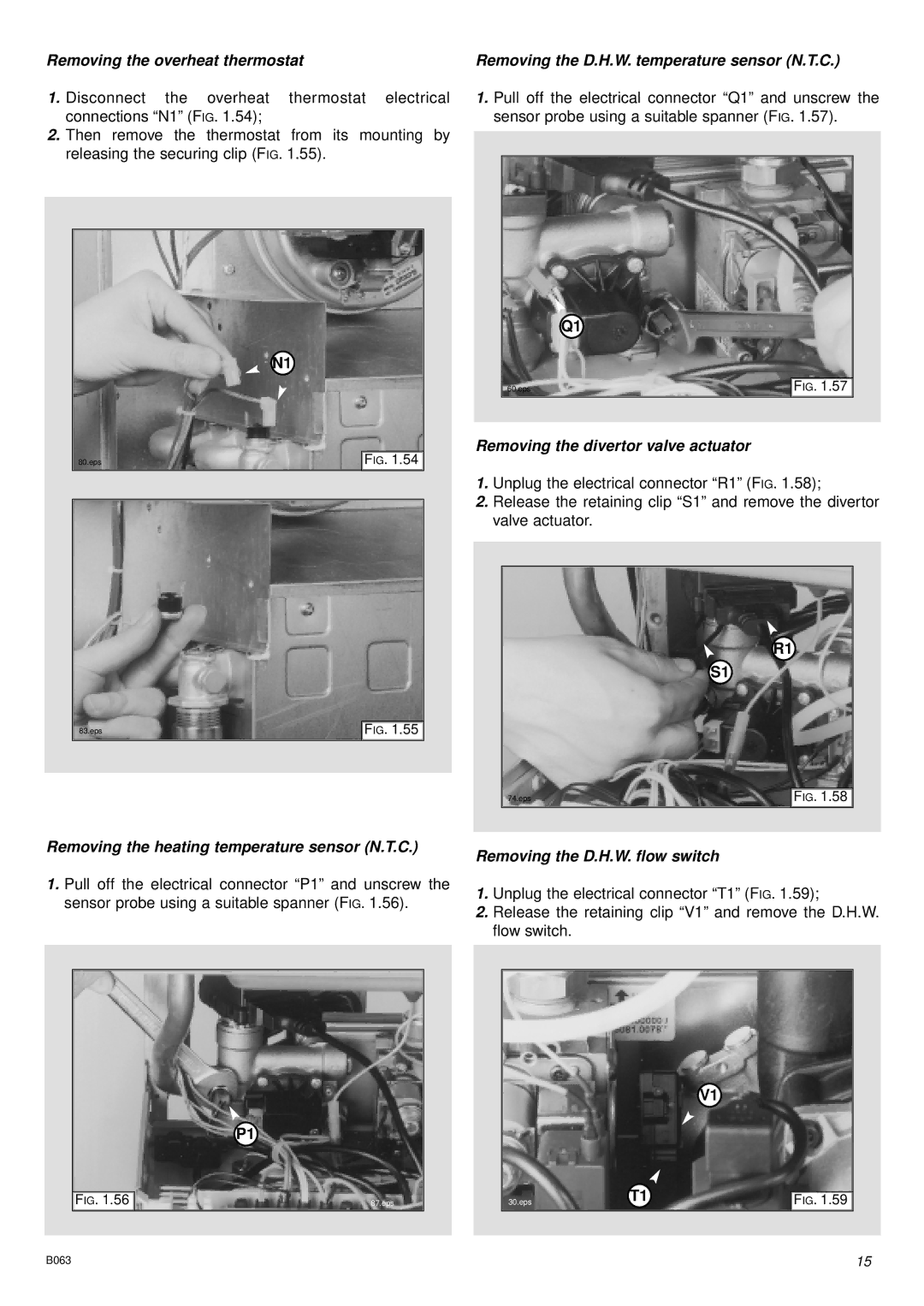
To dismantle the front casing panel it is necessary to:

1 - Remove the two screws “B”;

2 - Lift the front casing panel up and forward.

FO013A

FO008A

16
Image 16
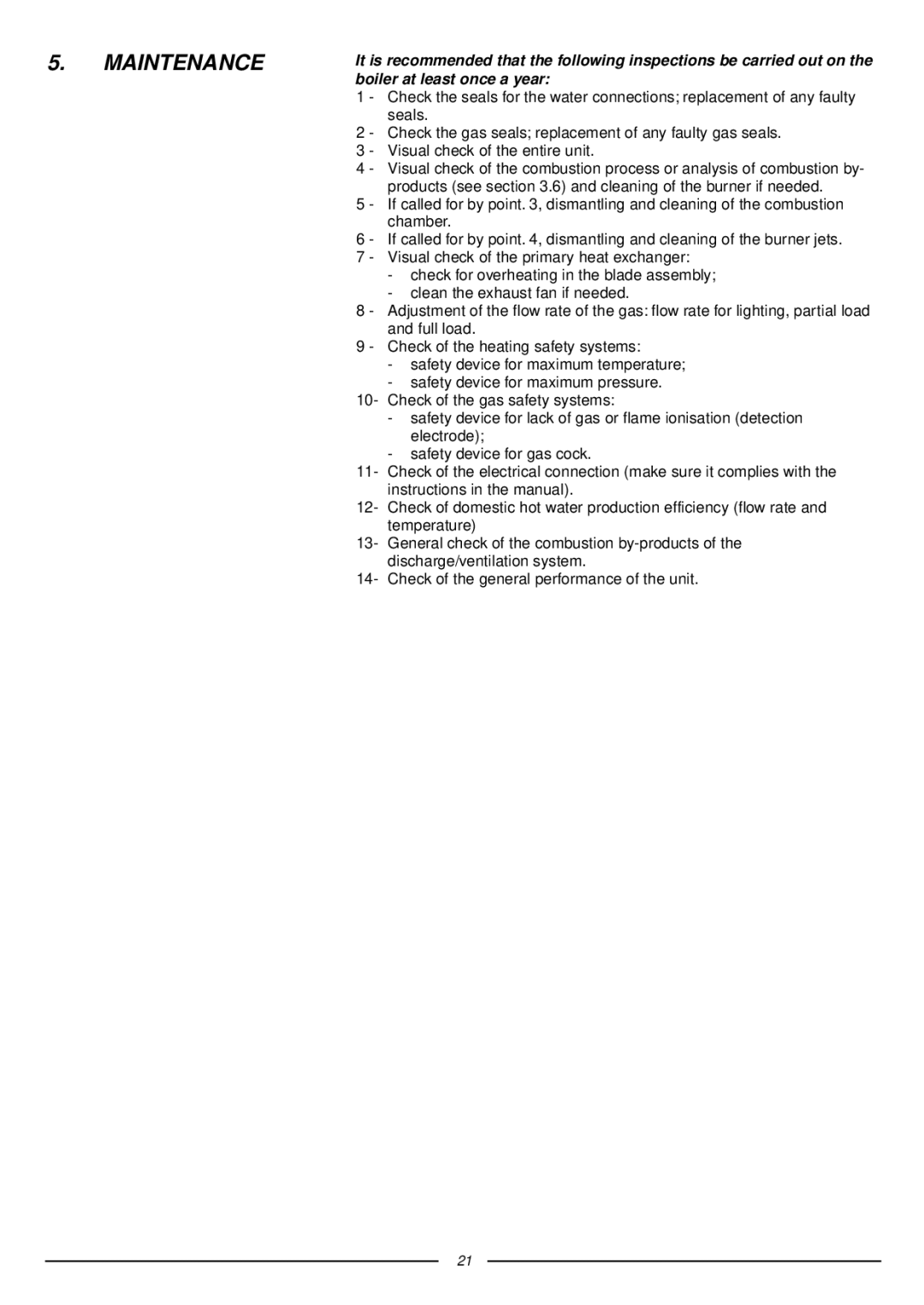
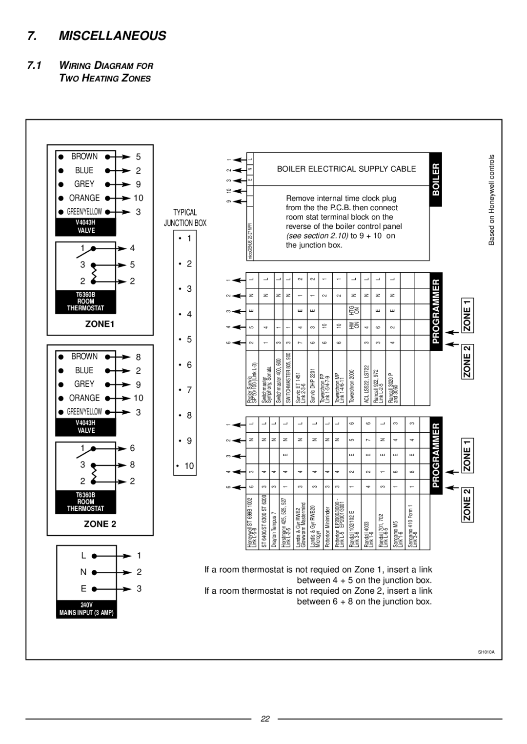
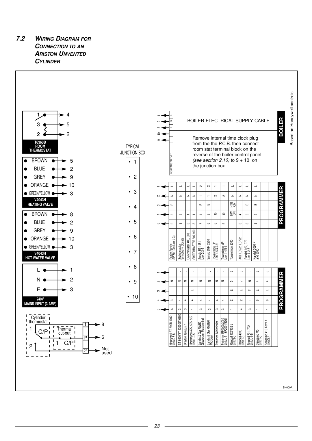
Contents Installation Instructions Type C Boilers Table of Contents General Information Overall View Installation Overall Dimensions Supply must be fused at 3 a Domestic Water Tonbridge Morley RoadKent TN9 1RA 80 mm Restrictor Extension Piping not insulated Piping insulated SystemsRestrictor No Restrictor Extension Piping not insulated Piping insulatedCalculating the lengths of the pipes, Electrical Diagram Central Heating Return Commissioning Control Panel Initial START-UP Operational Adjustments Status ANTI-FROST Device GAS Adjustments Methane Liquid Gas ButaneG20 Gas G30 16.0Maintenance Miscellaneous BoilerProgrammer Technical Information Technical Service Hot Line 01494Manufacturer Merloni TermoSanitari SpA Italy Servicing Instructions Type C Boilers Fault Finding Servicing Instructions Removing the front panelRemoving the sealed chamber frontal cover Removing the side panelsRemoving the burner and jets Removing the combustion coverRemoving the electrodes Removing the main heat exchanger Removing the air pressure switch Removing the fanSetting the gas pressures Setting the minimum and the maximum power of the boilerSetting the maximum heating circuit power Setting pressure for soft ignitionRegulating the heating power for Butane gas G30 Regulating the heating power for Natural gas G20Regulating the heating power for Propane gas G31 Removing the spark generator Removing the gas valve Removing the D.H.W. secondary exchangerRemoving the main circuit flow switch Removing the safety valveRemoving the automatic air vent Removing the pump Removing the pressure gauge Removing the expansion vesselRemoving the D.H.W. temperature sensor N.T.C Removing the heating temperature sensor N.T.CRemoving the D.H.W. flow switch Removing the overheat thermostatChecking the fuses Removing the time clockRemoving the P.C.B Fault Finding Finding diagrams described in this chapterYES YES ∆ P 1.2 mbar YES Electrical Diagrams MicroGENUS 23/27 Mffi MicroGENUS 23/27 Mffi Ariston Page Manufacturer Merloni TermoSanitari SpA Italy Microgenus 27 Mffi Cod Part Code Description 998924 Panel combustion chamber front 571770 Main flow switch top cap