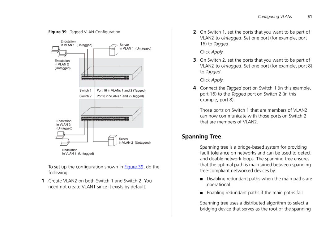
Figure 39 Tagged VLAN Configuration
To set up the configuration shown in Figure 39, do the following:
1Create VLAN2 on both Switch 1 and Switch 2. You need not create VLAN1 since it exists by default.
Configuring VLANs | 51 |
2On Switch 1, set the ports that you want to be part of VLAN2 to Untagged. Set one port (for example, port 16) to Tagged.
Click Apply.
3On Switch 2, set the ports that you want to be part of VLAN2 to Untagged. Set one port (for example, port 8) to Tagged.
Click Apply.
4Connect the Tagged port on Switch 1 (in this example, port 16) to the Tagged port on Switch 2 (in this example, port 8).
Those ports on Switch 1 that are members of VLAN2 can now communicate with those ports on Switch 2 that are members of VLAN2.
Spanning Tree
Spanning tree is a
■Disabling redundant paths when the main paths are operational.
■Enabling redundant paths if the main paths fail.
Spanning tree uses a distributed algorithm to select a bridging device that serves as the root of the spanning