SFP Operation 27
■
This transceiver uses Category 5 copper cabling with
If the SFP transceiver is faulty, it will not operate within the Switch. See “Solving Hardware Problems” on page 55.
3Com recommends that you only use SFPs supplied by 3Com. If the SFP transceiver is invalid it will not be recognized by the Switch.
Use the following sequence of steps to activate the SFP ports:
1The SFP transceiver is keyed and there is only one way in which it can be installed correctly. It is not necessary to
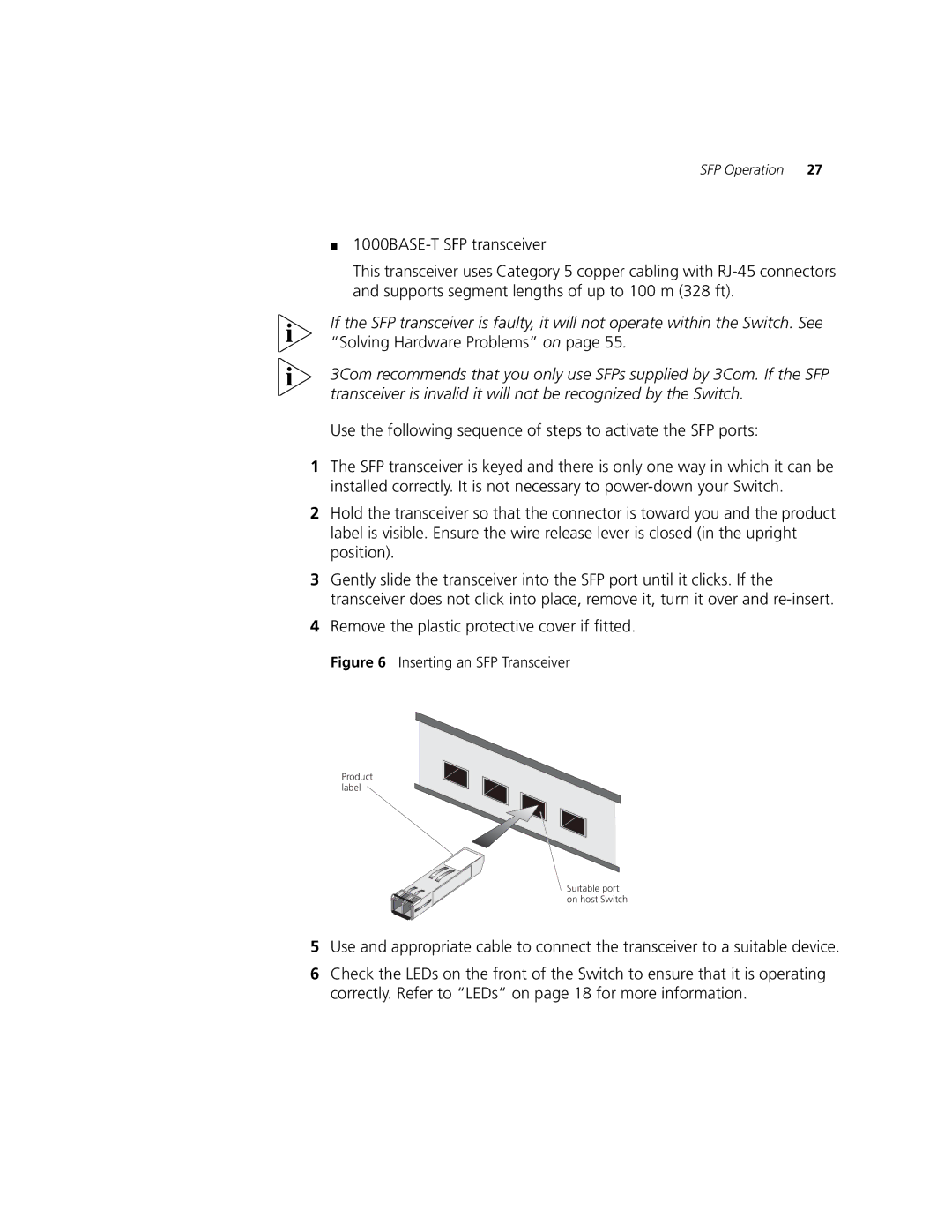
2Hold the transceiver so that the connector is toward you and the product label is visible. Ensure the wire release lever is closed (in the upright position).
3Gently slide the transceiver into the SFP port until it clicks. If the transceiver does not click into place, remove it, turn it over and
4Remove the plastic protective cover if fitted.
Figure 6 Inserting an SFP Transceiver
Product label
Suitable port on host Switch
5Use and appropriate cable to connect the transceiver to a suitable device.
6Check the LEDs on the front of the Switch to ensure that it is operating correctly. Refer to “LEDs” on page 18 for more information.