Switch
Table 3 Hardware Features (continued)
Feature | Switch 4200G |
|
|
Mounting | |
Clustering | Up to 16 units can be linked together (15 members and |
| 1 commander) |
|
|
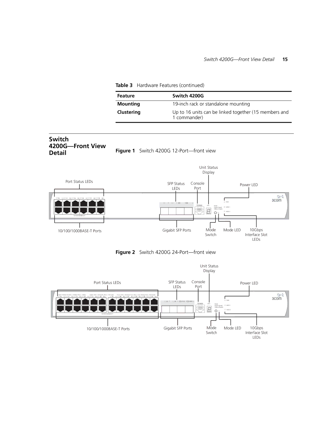
Switch 4200G—Front View
Detail | Figure 1 Switch 4200G |
|
| |
|
| Unit Status |
|
|
|
| Display |
|
|
Port Status LEDs | SFP Status Console | Power LED | ||
| ||||
| LEDs | Port | ||
|
|
| ||
|
|
| PWR |
|
|
| Mode | MOD 1 |
|
|
| Green=Speed |
| |
|
| Yellow=Duplex |
|
|
|
|
| MOD 2 |
|
|
|
|
| |
Gigabit SFP Ports | Mode | Mode LED | 10Gbps | |
|
| Switch |
| Interface Slot |
LEDs
Figure 2 Switch 4200G 24-Port—front view
Unit Status
Display
Port Status LEDs | SFP Status | Console | Power LED |
| LEDs | Port |
|
Speed: | Duplex: Green = Full Duplex, Yellow = Half Duplex | Power: Green = Delivering Power, Yellow = Fault, Flashing Green = Over Budget |
|
|
|
|
|
| 25 | 26 | 27/25 | 28/26 | PWR |
|
|
| ||||
|
|
|
|
| Mode | MOD 1 |
|
|
|
|
| Green=Speed | |
|
|
|
|
| Yellow=Duplex |
|
|
|
|
|
|
| MOD 2 |
|
|
|
|
|
|
Gigabit SFP Ports | Mode | Mode LED | 10Gbps | |
|
| Switch |
| Interface Slot |
|
|
|
| LEDs |
