Model ER
Release 5.0.00 / Updated
GUIDE
QUICK START
Trademarks
8e6 Enterprise Reporter Quick Start Guide
Install the Server
Contents
Service Information
Preliminary Setup Procedures
Regulatory Specifications and Disclaimers
“H” Server Specifications
Appendix SCSI Connected Storage Device
ER Enterprise Reporter Introduction
Conventions Used in this Document
About this Document
8e6 Taiwan
Service Information
Procedures
8e6 Corporate Headquarters USA
Unpack the Unit from the Carton
Preliminary Setup Procedures
Select a Site for the Server
Inside front end of U-shaped
Install the “H” Server Bezel
Front of bezel
Outside of left inner rail
E. Take up the free end of the bezel and also the loosened inner rail
G. Slide the inner rail forward beneath the clips to lock it in place
Rack Mount the Server
Rack Setup Precautions
Rack Mount Instructions for non-“H” Servers
Rack Setup Suggestions
Identify the Sections of the Rack Rails
Install the Rack Rails
Install the Chassis Rails
Installing the Server into a Telco Rack
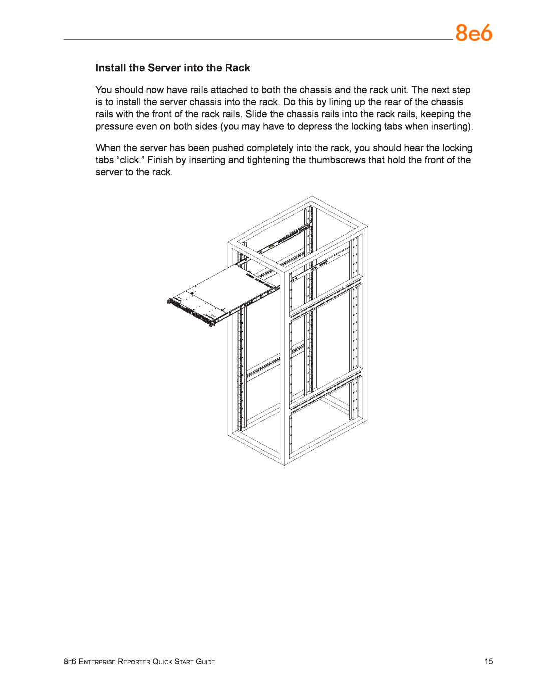
Install the Server into the Rack
You should have received two rack rail assemblies with the 8e6 server unit. Each of these assemblies consists of two sections An inner fixed chassis rail that secures to the unit A, and an outer fixed rack rail that secures directly to the rack itself B. Two pairs of short brackets to be used on the front side of the outer rails are also included
Identify the Sections of the Rack Rails
Rack Setup Suggestions
Install the Inner Rails
Install the Outer Rails
Rack Mount Instructions for “H” Servers
8e6 Enterprise Reporter Quick Start Guide
Install the Server into the Rack
If you are installing the 8e6 server unit into a Telco type rack, follow the directions given on the previous page for rack installation. The only difference in the installation proce- dure will be the positioning of the rack brackets to the rack. They should be spaced apart just enough to accommodate the width of the Telco rack
Installing the Server into a Telco Rack
Power Supply Precautions
Check the Power Supply
Server Operation and Maintenance Precautions
General Safety Information
Electrical Safety Precautions
AC Power Cord and Cable Precautions
Motherboard Battery Precautions
Administrator Console Setup Requirements
Step 1 Setup Procedures
Install the Server
Quick Start Setup Requirements
Serial Console Setup
Step 1A Quick Start Setup Procedures
Storage Device Setup for Attached Storage Units
Monitor and Keyboard Setup
HyperTerminal Setup Procedures
8e6 Enterprise Reporter Quick Start Guide
D. Specify the following session settings Bits per second Data bits
Parity None Stop bits Flow control Hardware
E. Click OK to connect to the HyperTerminal session
G. Click the Settings tab, and at the Emulation menu select “VT100”
Quick Start menu screen
Login screen
Quick Start menu administration menu
Log Off, Disconnect the Peripherals
System Status screen
Storage Device Setup for Attached Storage Units
Step 1B Console Setup Procedures
Preliminary Setup
Workstation Configurations
A. Plug one end of the CAT-5E crossover cable into the ER’s LAN 1 port
Link the Workstation to the ER
The Boot Up Process
Access the Internet
Network Setup
Log in to the Administrator Console
C. Click OK to go to the main screen of the Administrator console
Network Settings
8e6 Enterprise Reporter Quick Start Guide
G. Enter the Second DNS IP address of the fallback DNS
Regional Setting Time Zone
Regional Setting NTP Servers
Regional Setting Language
Physically Connect the ER to the Network
Access the Internet
Step 2 Change User Name and Password, Set Self- Monitoring
C. Enter a User Name and Password
Change User Name and Password
C. Enter the Master Administrator’s E-Mail Address
Set Self-Monitoring
D. Select 8e6 Enterprise Reporter, and then click Save
Step 3 R3000 Configuration
Step 4 Client Workstation Configuration
Step 5 Launch the ER Client
F. Enter the Password, and Confirm Password
Conclusion
Important Information about using the ER in the Evaluation Mode
Administrator Console, Expiration Screen
ER Client, ER Server Statistics Window
Value
Physical Specifications
Non-“H” Server Specifications
Specification
ER3-200
Hardware Component Specifications
Internal Product Specifications
ER3-100
LED Indicator Key
Front Panel LED Indicators and Buttons
Diagrams and Descriptions
LED Indicators and Buttons
Physical Specifications
“H” Server Specifications
ERH-100 Value
ERH-200 Value
Internal Product Specifications
ERH-100
ERH-200
Hardware Component Specifications
Front of Chassis Control Panel
Rear of Chassis
Electromagnetic Compatibility EMC
Regulatory Specifications and Disclaimers
Safety Compliance
Declaration of the Manufacturer or Importer
8e6 Enterprise Reporter Quick Start Guide
Electromagnetic Compatibility Class A Notice
Industry Canada Equipment Standard for Digital Equipment ICES-003
China Compulsory Certification CCC - China
European Community Directives Requirement CE
EC Declaration of Conformity
Declaration of Conformity
Unpack the Unit from the Carton
Preliminary Setup Procedures
Other Required Installation Items
Appendix SCSI Connected Storage Device
Rack Mount the Server
Rack Setup Precautions
Rack Mount Components
Step
Step
Attach inner slide rail to chassis using 3 screws as shown
Appendix SAN Installation
Step
NOTE Make sure the flange is on the bottom edge
Attach left and right rear long extended brackets to the outer rail using 2 screws, 2 washers, and 2 nuts for each bracket
Step
Step
Attach outer rail to chassis using 4 screws and cage nuts per rail, 2 at each end
Step
Link the ER Unit with the SCSI Connected Device
Install the Unit
Shut Down the Storage Device Unit
Shut Down, Restart Procedures
Restart the Storage Device Unit
Appendix SAN Installation
Physical Components
8e6 Enterprise Reporter Quick Start Guide
Power Supply Status
Temperature and Ventilation Status
LED Display
Disk Drive Activity
Management Alarm
Disc Drive Alarm
Silence Button
SATABoy Model Value
Specifications
Table 1 Physical Specifications
Table 2 Hardware Component Specifications
8e6 Enterprise Reporter Quick Start Guide
Appendix SAN Installation
Satellite Office
8e6 Corporate Headquarters USA
828 West Taft Avenue Orange, CA 92865-4232 Tel 714.282.6111 or
Fax 714.282.6116 Sales/Technical Support 714.282.6117 General Office