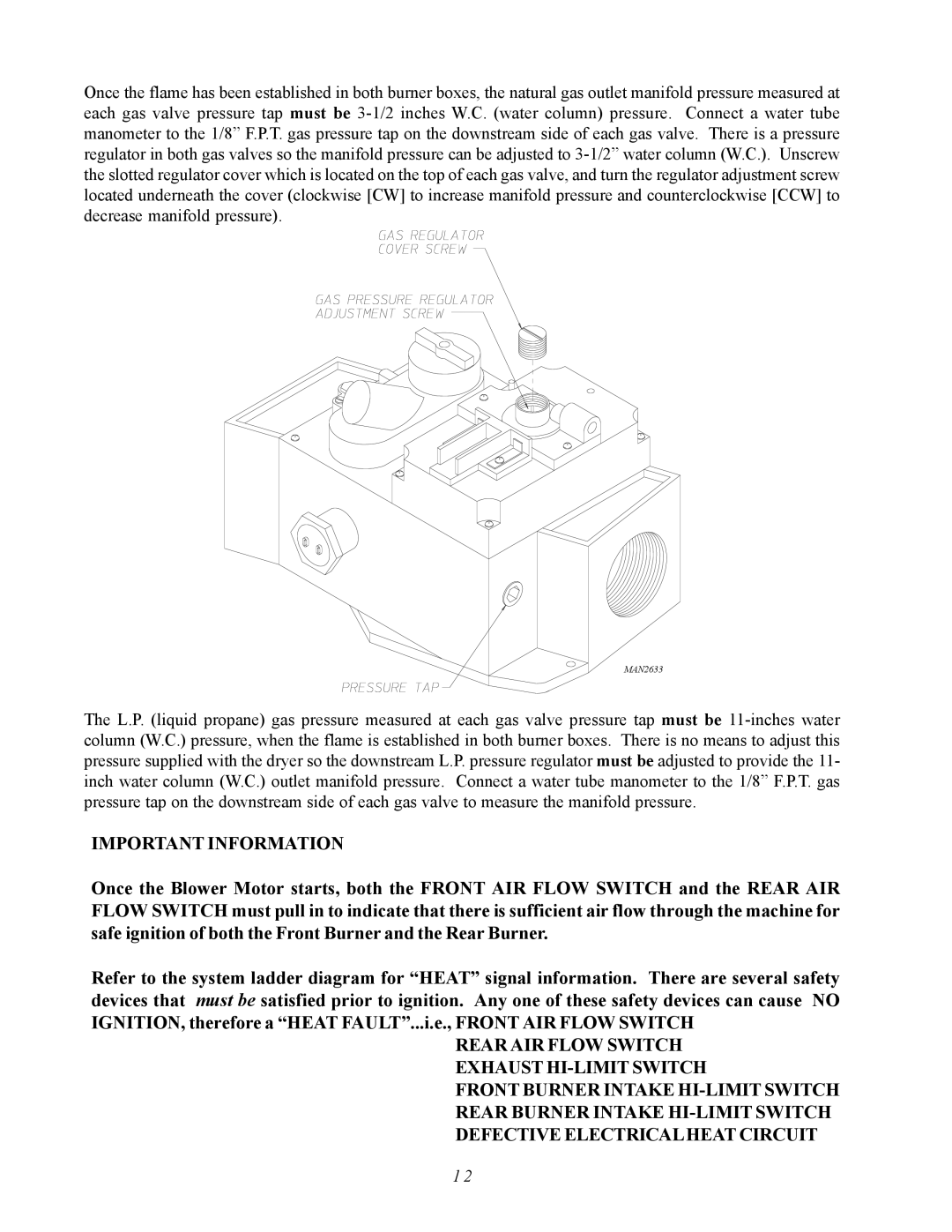
Once the flame has been established in both burner boxes, the natural gas outlet manifold pressure measured at each gas valve pressure tap must be 3-1/2 inches W.C. (water column) pressure. Connect a water tube manometer to the 1/8” F.P.T. gas pressure tap on the downstream side of each gas valve. There is a pressure regulator in both gas valves so the manifold pressure can be adjusted to 3-1/2” water column (W.C.). Unscrew the slotted regulator cover which is located on the top of each gas valve, and turn the regulator adjustment screw located underneath the cover (clockwise [CW] to increase manifold pressure and counterclockwise [CCW] to decrease manifold pressure).
MAN2633
The L.P. (liquid propane) gas pressure measured at each gas valve pressure tap must be 11-inches water column (W.C.) pressure, when the flame is established in both burner boxes. There is no means to adjust this pressure supplied with the dryer so the downstream L.P. pressure regulator must be adjusted to provide the 11- inch water column (W.C.) outlet manifold pressure. Connect a water tube manometer to the 1/8” F.P.T. gas pressure tap on the downstream side of each gas valve to measure the manifold pressure.
IMPORTANT INFORMATION
Once the Blower Motor starts, both the FRONT AIR FLOW SWITCH and the REAR AIR FLOW SWITCH must pull in to indicate that there is sufficient air flow through the machine for safe ignition of both the Front Burner and the Rear Burner.
Refer to the system ladder diagram for “HEAT” signal information. There are several safety devices that must be satisfied prior to ignition. Any one of these safety devices can cause NO IGNITION, therefore a “HEAT FAULT”...i.e., FRONT AIR FLOW SWITCH
REAR AIR FLOW SWITCH EXHAUST HI-LIMIT SWITCH
FRONT BURNER INTAKE HI-LIMIT SWITCH
REAR BURNER INTAKE HI-LIMIT SWITCH
DEFECTIVE ELECTRICALHEAT CIRCUIT