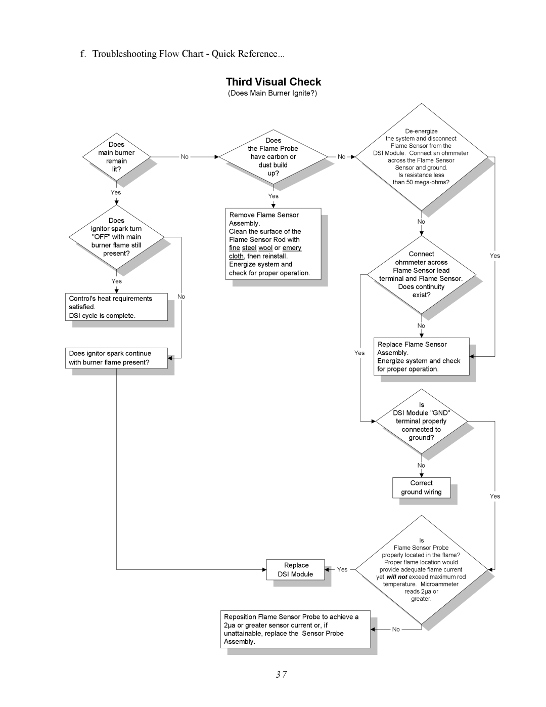
f. Troubleshooting Flow Chart - Quick Reference...
Does
main burner
remain
lit?
Yes
No
Third Visual Check
(Does Main Burner Ignite?)
|
|
|
|
|
|
| |
Does |
|
|
| the system and disconnect | |||
the Flame Probe |
|
|
| Flame Sensor from the | |||
|
|
| DSI Module. Connect an ohmmeter | ||||
have carbon or |
|
|
| ||||
| No |
| |||||
|
| across the Flame Sensor | |||||
dust build |
|
|
| ||||
|
|
| Sensor and ground. | ||||
| up? |
|
|
| |||
|
|
|
| Is resistance less | |||
|
|
|
|
|
|
| than 50 |
|
|
|
|
|
|
|
|
| Yes |
|
|
|
|
| |
|
|
|
|
|
|
|
|
Does
ignitor spark turn "OFF" with main burner flame still present?
Yes
Control's heat requirements satisfied.
DSI cycle is complete.
Does ignitor spark continue with burner flame present?
No
Remove Flame Sensor Assembly.
Clean the surface of the Flame Sensor Rod with fine steel wool or emery cloth, then reinstall.
Energize system and check for proper operation.
Yes
| Replace |
|
|
|
|
| Yes | ||
| DSI Module |
|
| |
|
|
|
| |
|
|
| ||
|
|
|
|
|
No
Connect
ohmmeter across Flame Sensor lead terminal and Flame Sensor. Does continuity
exist?
No
Replace Flame Sensor Assembly.
Energize system and check for proper operation.
Is
DSI Module "GND" terminal properly connected to ground?
No
Correct
ground wiring
Is
Flame Sensor Probe properly located in the flame? Proper flame location would provide adequate flame current yet will not exceed maximum rod temperature. Microammeter reads 2µa or
greater.
Yes
Yes
Reposition Flame Sensor Probe to achieve a |
|
|
|
2µa or greater sensor current or, if |
|
|
|
|
| No | |
unattainable, replace the Sensor Probe |
|
| |
|
|
| |
Assembly. |
|
|
|
|
|
|
|
3 7
