2)Ignitor and Flame-Probe Assembly
The ignitor and flame-probe assembly consists of a ceramic insulated ignitor electrode, a ground rod, and a ceramic insulated flame-probe electrode. The GAP between the ignitor electrode and the ground rod is set, and must be maintained at 1/8" +/- 1/32" (.1250 +/- .03121).When the DSI (Direct Spark Ignition) module provides the high synchronous spark (14,000 volts) through the high voltage (HV) lead, a spark is produced over the GAP. When this spark is produced, the gas valve is opened. Upon ignition, the flame probe electrode (of the ignitor and flame-probe assembly) has high voltage provided to it that supplies a small current to ground through the flame. Once the current is sensed, it initializes the DSI module to sustain the gas flow (from the gas valve).
IMPORTANT: THE GAP SETTING ON THE IGNITOR AND
FLAME-PROBE ASSEMBLY IS CRITICAL.
a) DSI Ignitor and Flame-Probe Assembly Adjustments
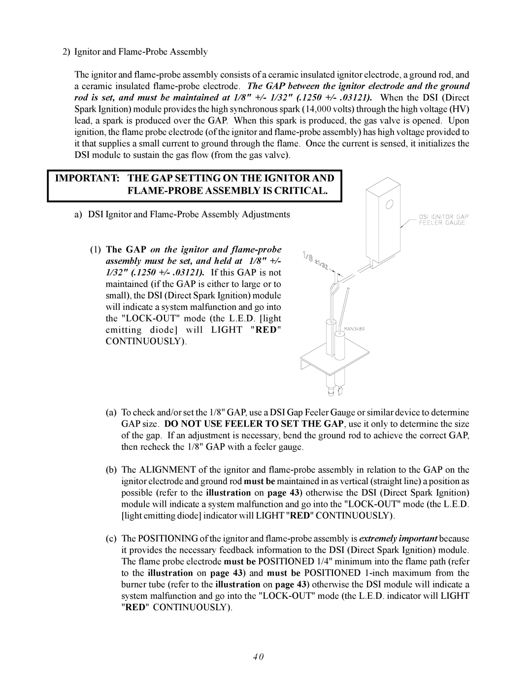
(1)The GAP on the ignitor and flame-probe assembly must be set, and held at 1/8" +/-
1/32" (.1250 +/- .03121).If this GAP is not maintained (if the GAP is either to large or to small), the DSI (Direct Spark Ignition) module will indicate a system malfunction and go into the "LOCK-OUT" mode (the L.E.D. [light emitting diode] will LIGHT "RED"
CONTINUOUSLY).
(a)To check and/or set the 1/8" GAP, use a DSI Gap Feeler Gauge or similar device to determine GAP size. DO NOT USE FEELER TO SET THE GAP, use it only to determine the size of the gap. If an adjustment is necessary, bend the ground rod to achieve the correct GAP, then recheck the 1/8" GAP with a feeler gauge.
(b)The ALIGNMENT of the ignitor and flame-probe assembly in relation to the GAP on the ignitor electrode and ground rod must be maintained in as vertical (straight line) a position as possible (refer to the illustration on page 43) otherwise the DSI (Direct Spark Ignition) module will indicate a system malfunction and go into the "LOCK-OUT" mode (the L.E.D. [light emitting diode] indicator will LIGHT "RED" CONTINUOUSLY).
(c)The POSITIONING of the ignitor and flame-probe assembly is extremely important because it provides the necessary feedback information to the DSI (Direct Spark Ignition) module. The flame probe electrode must be POSITIONED 1/4" minimum into the flame path (refer to the illustration on page 43) and must be POSITIONED 1-inch maximum from the burner tube (refer to the illustration on page 43) otherwise the DSI module will indicate a system malfunction and go into the "LOCK-OUT" mode (the L.E.D. indicator will LIGHT "RED" CONTINUOUSLY).