Manuals
/
Addlogix
/
Computer Equipment
/
Printer
Addlogix
iDP-3410
user manual
Star International
Models:
iDP-3410
1
120
152
152
Download
152 pages
21.01 Kb
117
118
119
120
121
122
123
124
Specification
Electrical Characteristics
Install
Appendix 1. Block Diagram
Input and Output Signals
Details of Errors
Connecting AC Adapter
Maintenance
Connectors Pin Configuration
Preset Jumper Setting
Page 120
Image 120
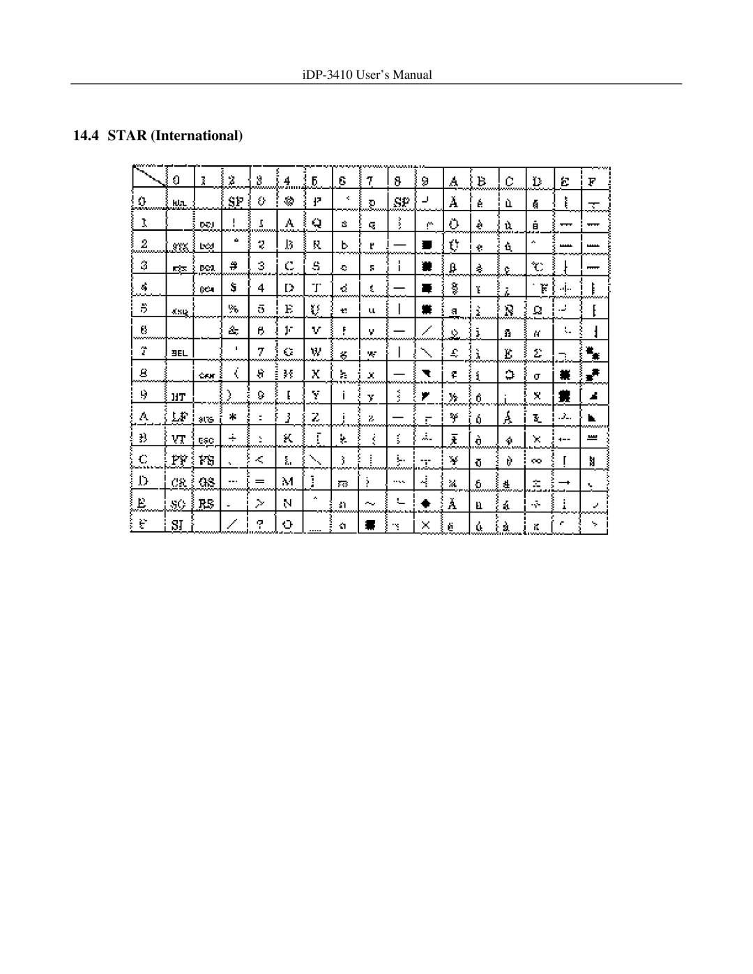
iDP-3410
User’s Manual
14.4 STAR (International)
Page 119
Page 121
Page 120
Image 120
Page 119
Page 121
Contents
Rev.1.00 Newly issued on 20.Oct.1998
Citizen
LVD
EMC
Important Safety Instructions
Lärmemission kleiner 70dBA
Sicherheitshinweis
IDP-3410 User’s Manual
Safety Precautions Be Sure to Observe
Page
Precautions for Installation
Precautions for Handling
Daily Maintenance
Contents
Drawer KICK-OUT Connector and Power Connector
Appendix
German
145
Basic Specifications
Features
Outline
Unpacking
Cord
Basic Specifications
Fcca
TUV GS
Paper Specification
Recommended Paper
Connecting AC Adapter
Outer Appearance and Component Parts Operation
Page
Connecting Interface Cable
Connecting Drawer Kick-Out Connector
Setting the Cassette Ribbon
Inserting the Paper
Page
How to Remove Remaining Paper Roll
Removing Paper Jam
Operation Panel and Display of Error
Details of Errors
Operation Flow at Power-on
DIP Switch Setting
Location of DIP Switch
DIP Switches Setting
DTR/DSR XON/XOFF
Preset Jumper Setting
Mode Setting Method
Location of Preset Jumper
Preset Jumper Table
Input Buffer Backup Function
Input Buffer Backup
Buffer Size
Clearing the Input Buffer
Specifications
Connectors Pin Configuration
Parallel Interface
Input and Output Signals
Select
Electrical Characteristics
Serial Interface
Data Receiving Control
Logic 0 +3 V ∼ +12
CBM Star ECS/POS TXD RXD RTS DSR GND PE HI-LEVEL RCH Fault
DTR Reset
Input and Output Signals
Data Configuration
Error Detection
∙RESET
∙PE
∙GND
∙FG
Drawer KICK-OUT Connector and Power Connector
Specifications of Drawer Kick-Out Connector
Drive Circuit
Specifications of Power Supply Connector
Maintenance and Service
Print Control Functions
ESC
ESC O
1BH 4FH
BEL
XXX
FF n
DC1
IDP-3410 User’s Manual Mixed in one line
DC3
ESC ∗ n1 n2
ESC − n
ESC
ESC C n
ESC N n
ESC f
ESC t n
ESC BEL n1 n2
BEL
SUB
ESC R n
ESC & 0 n1 n2 m0 m1 ... m5 m6 m7 m8 m9 n2 n1 +
ESC % n
ESC ⁄ n data CR or LF
ESC DC3 n
Function Printing the message Code 1BH 13H n Range ≤ n ≤
ESC DC2 n1 n2
GS ∗ n1 n2 d n1 × n2 ×
GS ⁄ m
1BH
ESC NOP 1BH
ESC M NOP 1BH 4DH ESC P
ESC NOP 1BH 3AH
1EH Can
DC3
DC1
ESC @
ESC R n
DC4
ESC − n
Line
ESC z
ESC a n
ESC C 0 n
Page
ESC B nk NUL
ESC l n
ESC Q n
Page
ESC D n k NUL
As regular one
ESC
ESC K n1 0 m1 m2
ESC L n1 n2 m1 m2
ESC h n
ESC & O n1 n2 m0 m1 m2 m3 m4 m5 m6 m7 m8 m9 n2 n1 +
ESC % n
Default N1 = n2 = 20 200ms
SUB
Can
ESC U n
ESC @
ENQ
STX
YES
FFH YES STX-ETX
RET
Page
ESC ⁄ n data CR or LF
Page
GS ∗ n1 n2 d n1 × n2 ×
13.3 ESC/POS Commands Command List
ESC NOP 1BH 3CH ESC @
Details
ESC n
ESC ! n
ESC % n
ESC & s n m ap s × am n +
ESC ∗ m n1 n2 d n1 + 256 × n2
≤ n2 ≤ ≤ d ≤ Outline
ESC
ESC D nk NUL
Spain
ESC c 5 n
ESC d n
ESC p m n1 n2
ESC r n
LOW High
With paper Near end Undefined
Print
ESC DC3 n
ESC DC2 n1 n2
GS ∗ n1 n2 d n1 × n2 ×
GS ⁄ m
Character Codes Table
CBM Domestic
CBM International
Star Domestic
Star International
Code
Katakana
Code
Code
Code
14.10Code
14.11Code
14.12Code
14.13Code
14.14Windows Code
14.15International Character Codes Table
Appendix 1. Block Diagram
CPU
Appendix 2. Outline Drawing
German
Vorsicht
Page
ZU Beachtende Sicherheitsmassregeln
Warnung Vorsicht
Warnung
Vorsichtsmassregeln FÜR DIE Aufstellung
Vorsichtsmassregeln FÜR DIE Handhabung
Tägliche Wartung
Betrieb
Anschluß des Netzteils
Page
Anschluß des Schnittstellenkabels
Anschluß des Ausschubmechanismussteckers der Geldschublade
Einsetzen der Farbbandkassette
Einlegen der Papierrolle
Page
Entfernen des restlichen Druckpapiers
Beseitigung von Papierstaus
Bedienfeld und Fehleranzeigelämpchen
Betriebsfluß beim Einschalten
Nein YES OFF
YES OFF
DIP-SCHALTER-EINSTELLUNG
Lage der DIP-Schalter
Nein
DIP-Schalter-Einstellungen
AUS
IDP-3410 User’s Manual DIP-Schalter Funktion
Einstellung DER VORWAHL-JUMPERSTECKER
Methode FÜR Moduseinstellung
Lage der Vorwahl-Jumperstecker
Vorwahl-Jumperstecker-Tabelle
Wartung UND Dienst
Top
Page
Image
Contents