iDP-3410 User’s Manual
ESC "∗" m n1 n2 [d] n1 + 256 × n2
[Function] | Specifying the bit image mode |
|
|
| |||||
[Code] | <1B>H <2A>H m n1 n2 [d] n1 + 256×2 |
|
|
| |||||
[Range] | m = 0, 1 |
|
|
|
|
|
| ||
| 0 ≤ n1 ≤ 255 |
|
|
|
|
| |||
| 0 ≤ n2 ≤ 3 |
|
|
|
|
|
| ||
| 0 ≤ d ≤ 255 |
|
|
|
|
| |||
[Outline] | This command specifies the bit image for the mode m as to the number of dots specified with | ||||||||
| n1 and n2. Divide the number of dots printed by 256 and assume its quotient to be n2 and | ||||||||
| remainder to be n1. Therefore, the number of horizontal dots will be n1 + 256 × n2. | ||||||||
| If the bit image data is entered beyond the dot positions printable in one line, the surplus data | ||||||||
| will be discarded. The following table shows the bit image modes for m. | ||||||||
|
|
|
|
|
|
|
|
|
|
|
|
|
|
|
|
| Horizontal Direction |
|
|
|
| m |
| Vertical | Dot Density | Adjacent Dot | Total Dots |
| |
|
|
|
| Dots | Setting |
| |||
|
|
|
|
|
|
|
| ||
|
| 0 |
|
| 8 | Single density | Allowed | 189 |
|
|
| 1 |
|
| 8 | Double density | Disallowed | 378 |
|
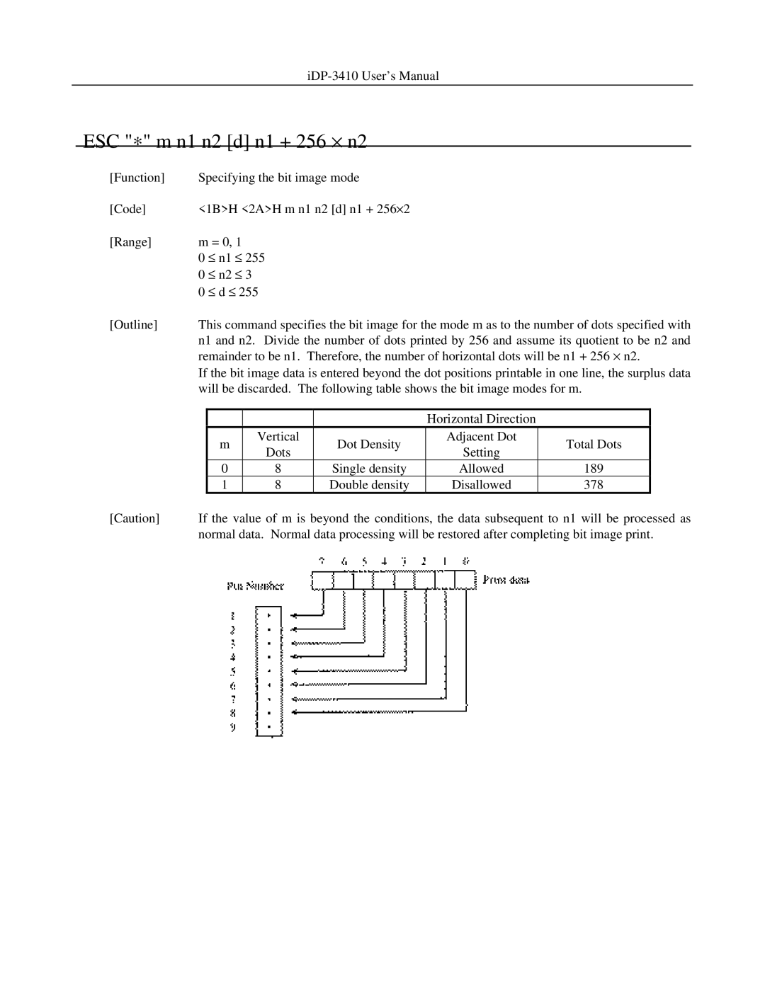
[Caution] | If the value of m is beyond the conditions, the data subsequent to n1 will be processed as | ||||||||
| normal data. Normal data processing will be restored after completing bit image print. | ||||||||