Compact Station
2.Establish the AC power connections and PE connections using the cable lug in accordance with the circuit diagram, and using the relevant tightening torque.
3.Remove any cable debris and tools from the equipment and replace the protective cover on the connection panel.
7.2.2ISO Small Distribution Box
| 5 |
1 | 6 |
| 7 |
2 | 8 |
3
4 | 5 |
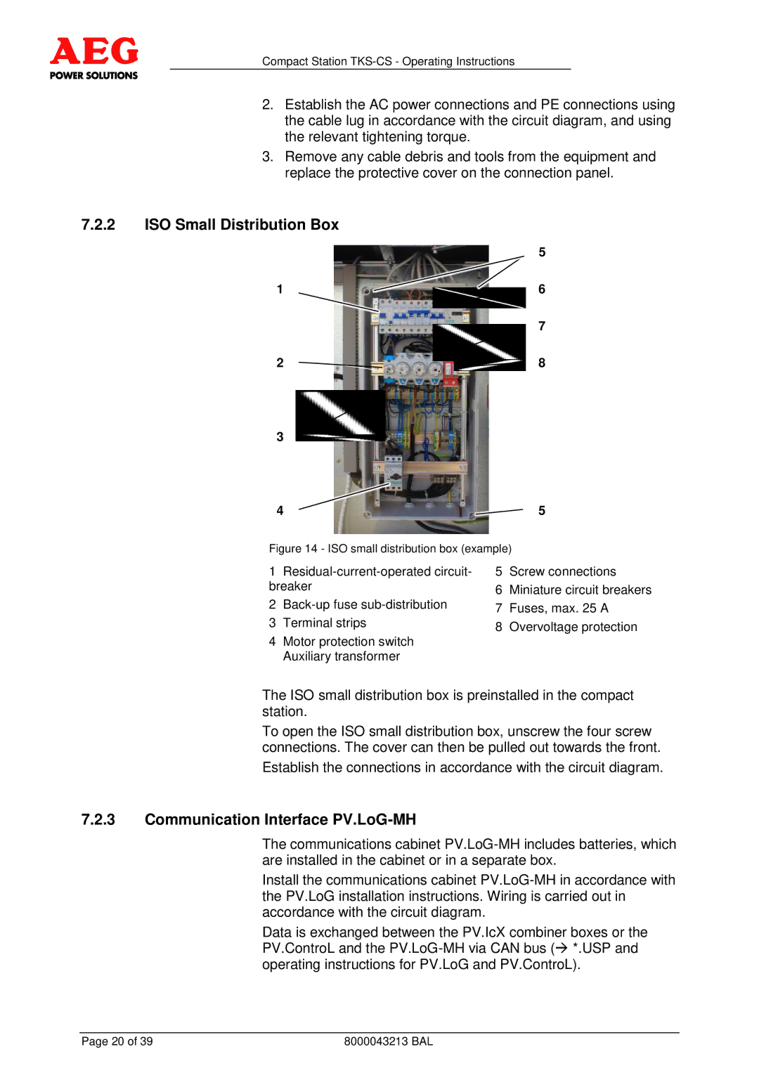
Figure 14 - ISO small distribution box (example)
1 | 5 | Screw connections | |
breaker | 6 | Miniature circuit breakers | |
2 | 7 | Fuses, max. 25 A | |
3 | Terminal strips | 8 | Overvoltage protection |
4Motor protection switch Auxiliary transformer
The ISO small distribution box is preinstalled in the compact station.
To open the ISO small distribution box, unscrew the four screw connections. The cover can then be pulled out towards the front.
Establish the connections in accordance with the circuit diagram.
7.2.3Communication Interface PV.LoG-MH
The communications cabinet
Install the communications cabinet
Data is exchanged between the PV.IcX combiner boxes or the PV.ControL and the
Page 20 of 39 | 8000043213 BAL |