Compact Station
5 Functional Description
PV.IcX | PV.SuN |
|
|
| |
max. 1 to 8 | optional |
|
|
|
|
|
|
|
|
| |
| PV.IcX |
| Transformer |
|
|
| max. 1 to 8 |
|
|
| |
| Transformer- |
|
|
| |
|
| Monitoring |
|
| |
|
|
|
| ||
| ~ |
| Transfer station |
| |
|
|
|
|
| |
|
| ~ |
| Radio and ripple |
|
|
|
| control / |
| |
|
|
| power utility |
| |
|
| interface |
| ||
PV.IcX | PV.SuN |
| 4 x relay | Switchgear | |
|
| Energy meter | |||
max. 1 to 8 | optional |
|
|
| |
|
|
|
| ||
![]() PV.ControL
PV.ControL
Transformer | Internet |
connection |
Monitoring
Transformer-
~
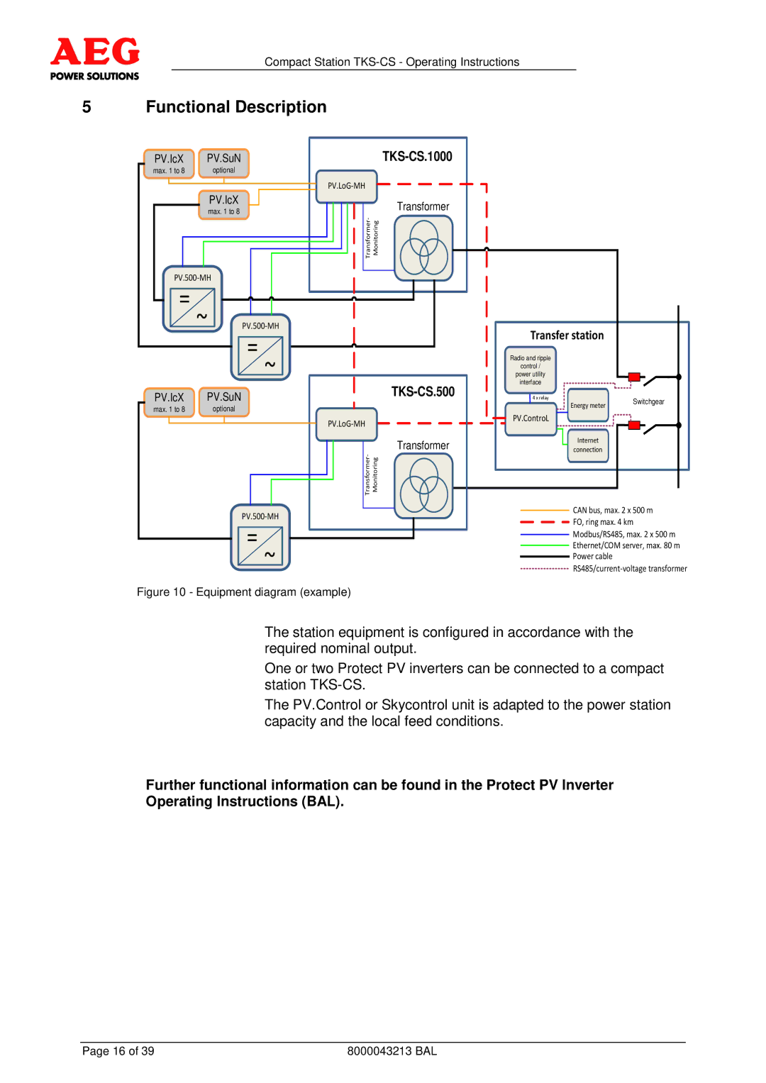
Figure 10 - Equipment diagram (example)
CAN bus, max. 2 x 500 m
![]() FO, ring max. 4 km
FO, ring max. 4 km
Modbus/RS485, max. 2 x 500 m Ethernet/COM server, max. 80 m Power cable
![]()
The station equipment is configured in accordance with the required nominal output.
One or two Protect PV inverters can be connected to a compact station
The PV.Control or Skycontrol unit is adapted to the power station capacity and the local feed conditions.
Further functional information can be found in the Protect PV Inverter Operating Instructions (BAL).
Page 16 of 39 | 8000043213 BAL |