Compact Station
No. H07V-K Name
[mm2]
170
295 Cable entry
370 Station housing
4 16
516 Communications cabinet
670
770 Transformer
Table 3 - Potential equalising strip
The central earthing system is preinstalled on the potential equalising strip in the compact station.
4.4Medium-Voltage System
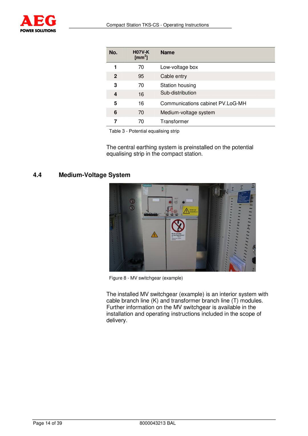
Figure 8 - MV switchgear (example)
The installed MV switchgear (example) is an interior system with cable branch line (K) and transformer branch line (T) modules. Further information on the MV switchgear is available in the installation and operating instructions included in the scope of delivery.
Page 14 of 39 | 8000043213 BAL |