Compact Station
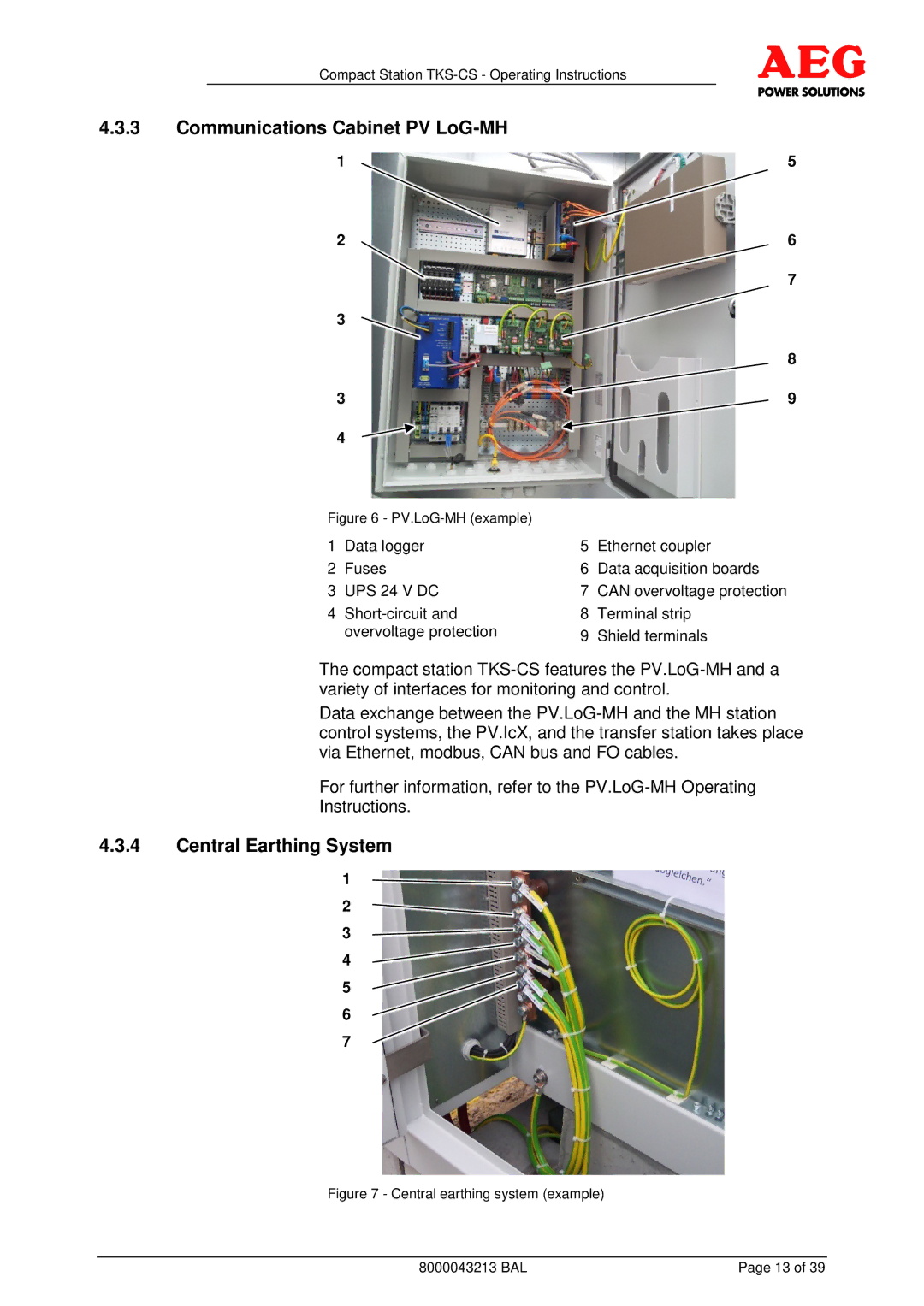
4.3.3Communications Cabinet PV LoG-MH
1 | 5 |
2 | 6 |
| 7 |
3 |
|
| 8 |
3 | 9 |
4 |
|
Figure 6 - |
|
| |
1 | Data logger | 5 | Ethernet coupler |
2 | Fuses | 6 | Data acquisition boards |
3 | UPS 24 V DC | 7 | CAN overvoltage protection |
4 | 8 | Terminal strip | |
| overvoltage protection | 9 | Shield terminals |
The compact station
Data exchange between the
For further information, refer to the
4.3.4Central Earthing System
1
2
3
4
5
6
7
Figure 7 - Central earthing system (example)
8000043213 BAL | Page 13 of 39 |