Chapter 4 Theory of Operation
Floating Logic
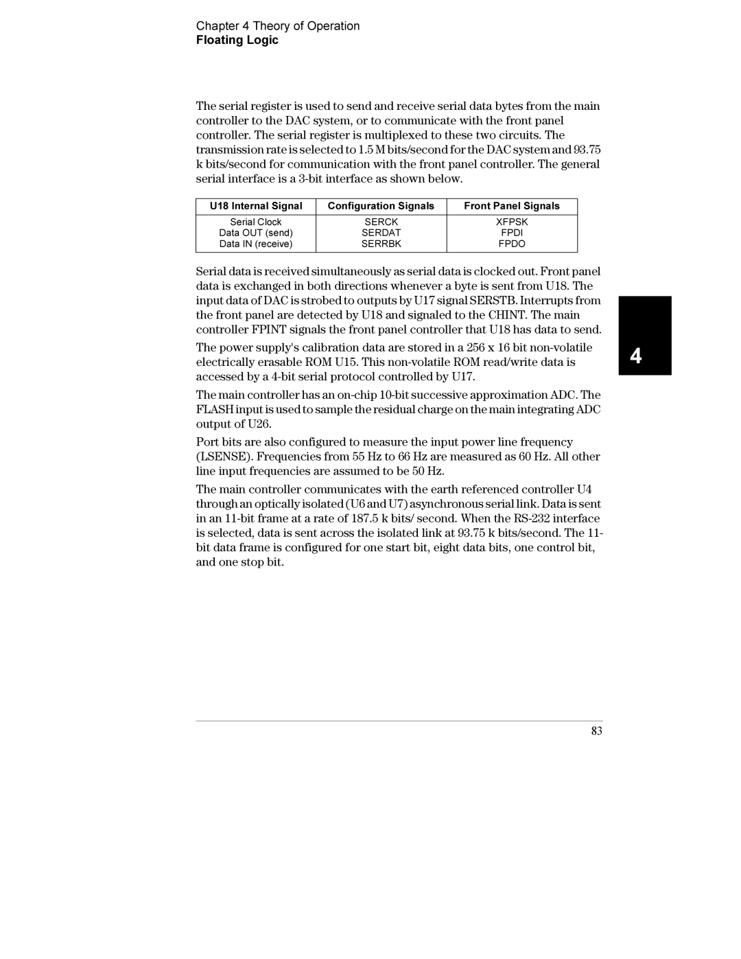
The serial register is used to send and receive serial data bytes from the main controller to the DAC system, or to communicate with the front panel controller. The serial register is multiplexed to these two circuits. The transmission rate is selected to 1.5 M bits/second for the DAC system and 93.75 k bits/second for communication with the front panel controller. The general serial interface is a
U18 Internal Signal | Configuration Signals | Front Panel Signals |
|
|
|
Serial Clock | SERCK | XFPSK |
Data OUT (send) | SERDAT | FPDI |
Data IN (receive) | SERRBK | FPDO |
|
|
|
Serial data is received simultaneously as serial data is clocked out. Front panel data is exchanged in both directions whenever a byte is sent from U18. The input data of DAC is strobed to outputs by U17 signal SERSTB. Interrupts from the front panel are detected by U18 and signaled to the CHINT. The main controller FPINT signals the front panel controller that U18 has data to send.
The power supply's calibration data are stored in a 256 x 16 bit
The main controller has an
Port bits are also configured to measure the input power line frequency (LSENSE). Frequencies from 55 Hz to 66 Hz are measured as 60 Hz. All other line input frequencies are assumed to be 50 Hz.
The main controller communicates with the earth referenced controller U4 through an optically isolated (U6 and U7) asynchronous serial link. Data is sent in an
83
4