N o t e
N o t e
Chapter 3 Calibration Procedures
General Calibration/Adjustment Procedure
General Calibration/Adjustment Procedure
The calibration procedures from the front panel are described in this section. For voltage calibration, disconnect all loads from the power supply and connect a DVM across the output terminals. For current calibration, disconnect all loads from the power supply, connect an appropriate current monitoring resistor (0.019) across the output terminals, and connect a DVM across the terminals of the monitoring resistor.
Note that the power supply should be calibrated after
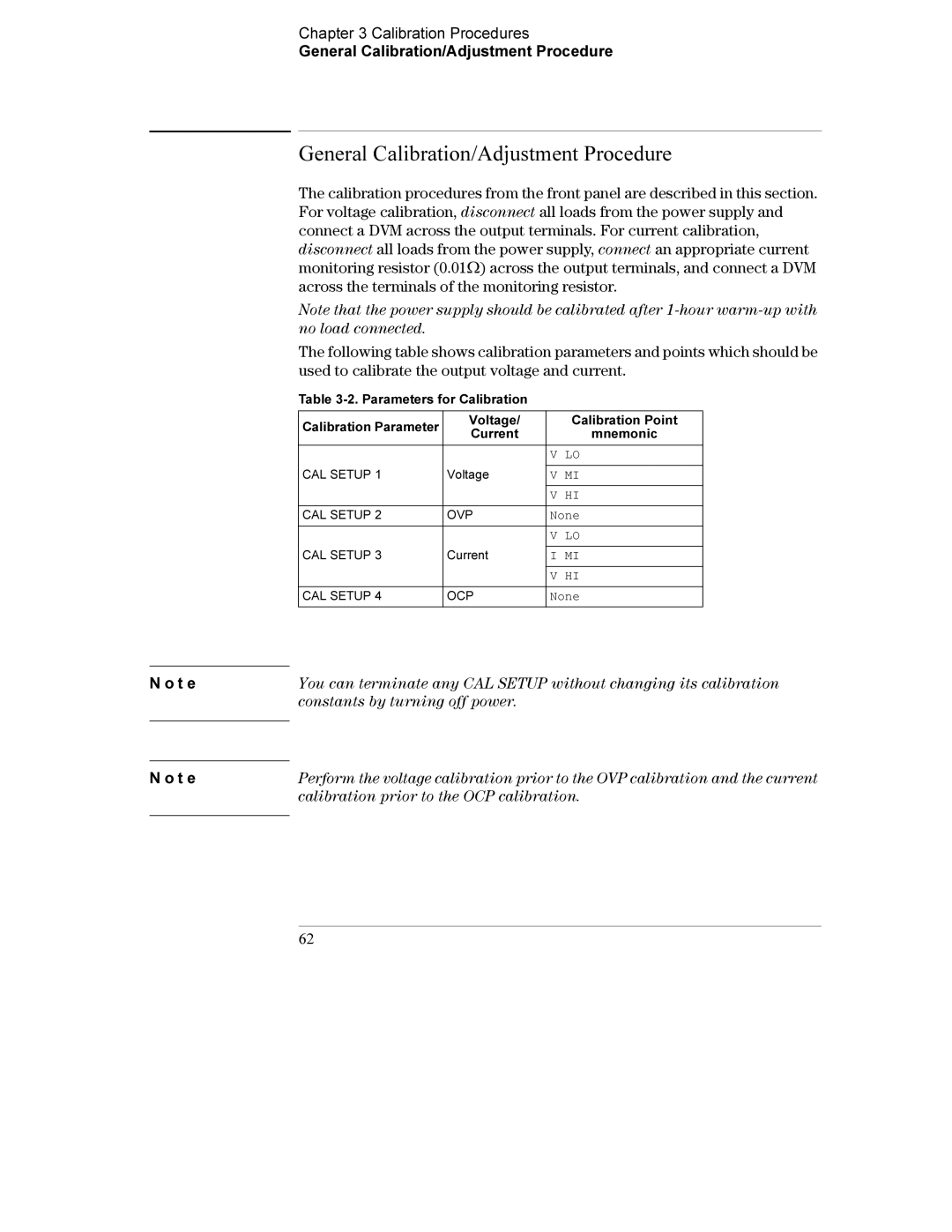
The following table shows calibration parameters and points which should be used to calibrate the output voltage and current.
Table
Calibration Parameter | Voltage/ | Calibration Point | |
Current | mnemonic | ||
| |||
|
|
| |
|
| V LO | |
CAL SETUP 1 | Voltage |
| |
V MI | |||
|
|
| |
|
| V HI | |
|
|
| |
CAL SETUP 2 | OVP | None | |
|
|
| |
|
| V LO | |
CAL SETUP 3 | Current |
| |
I MI | |||
|
|
| |
|
| V HI | |
|
|
| |
CAL SETUP 4 | OCP | None | |
|
|
|
You can terminate any CAL SETUP without changing its calibration constants by turning off power.
Perform the voltage calibration prior to the OVP calibration and the current calibration prior to the OCP calibration.
62
