Contents
BdiGDB
Introduction
Installation
Using bdiGDB
BDI2000 BDI Configuration
Troubleshooting Maintenance Trademarks
Appendices
Introduction
BDI2000
BDI Configuration
Connecting the BDI2000 to Target
Installation
For BDI Main / Target a connector signals see table on next
BDI Main / Target a Connector Signals
Jtag Test Reset
Changing Target Processor Type
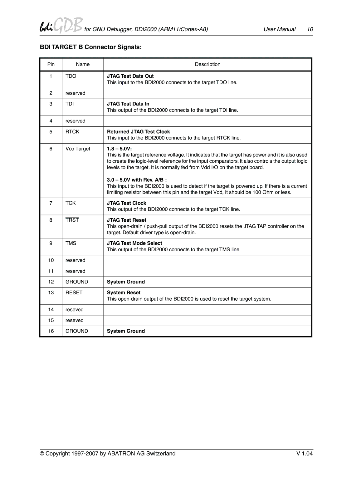
For Target B connector signals see table on next
Adaptive Clocking
BDI Target B Connector Signals
Returned Jtag Test Clock
Please switch on the system in the following sequence
External power supply Target system
Power Supply from Target System
142
Status LED «MODE»
Built in LED indicates the following BDI states
RS232 Connector
PC Host
BASE-T Connector
Ethernet communication
Name Description
Overview of an installation / configuration process
Installation of the Configuration Software
Activating Bootp
1 Configuration with a Linux / Unix host
Build the setup tool
Load/Update the BDI firmware/logic
Following the steps to bring-up a new BDI2000
file name without any path
Check configuration and exit loader mode
Transmit the initial configuration parameters
For more information about Tftp use man tftpd
2 Configuration with a Windows host
Ory / programmable logic
Recover procedure
Reassemble the unit as described in Appendix «Maintenance»
Testing the BDI2000 to host connection
Tftp server for Windows NT
Using bdiGDB
Principle of operation
Configuration File
Part Init
BdiGDB for GNU Debugger, BDI2000 ARM11/Cortex-A8
Format COFF, SREC, AOUT, BIN, ELF or ROM Example
Using a startup program to initialize the target system
ROM on the target, select ROM as the format
Format Coff
None
Part Target
Cputype ARM1136
Pushpull
RUN
Halt
Stop
Loadonly
Breakmode Hard
Soft
Hard
Core
Daisy chained Jtag devices
Low level Jtag scan chain configuration
Part Host
Prompt ARM11
Dump filename
Part Flash
BLOCK, CHIP, Unlock
Supported Flash Memories
AM29BX8 MIRRORX8, I28BX8 STRATAX8, AT49X8
Or use the Telnet unlock command
Tor. In other words, this is the size of one sector in bytes
Part Regs
Entry in the configuration file
Example for a register definition
Register definition file
Connecting to the target
Target setup
Debugging with GDB
GDB monitor command
Breakpoint Handling
Target serial I/O via BDI
Target DCC I/O via BDI
Telnet Interface
Command list
Dump
CP15 Cache Type CRn = 0, opcode2 =
CPxx Registers
Some examples CP15 ID register CRn = 0, opcode2 =
CP15 Invalidate I cache line CRn = 7, opcode2 = 1, CRm =
Multi-Core Support
Specifications
BASE-T
Environmental notice
Declaration of Conformity CE
Warranty
firmware can not be loaded
Troubleshooting
Problem
Possible reasons
Maintenance
Unplug the cables
Reinstallation
Trademarks
All trademarks are property of their respective holders