bdiGDB for GNU Debugger, BDI2000 | User Manual | 6 |
2 Installation
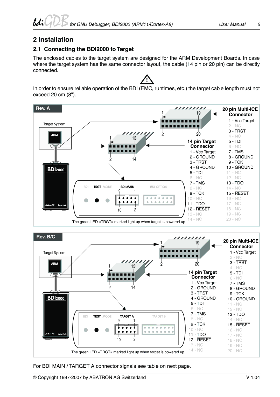
2.1 Connecting the BDI2000 to Target
The enclosed cables to the target system are designed for the ARM Development Boards. In case where the target system has the same connector layout, the cable (14 pin or 20 pin) can be directly connected.
!
In order to ensure reliable operation of the BDI (EMC, runtimes, etc.) the target cable length must not exceed 20 cm (8").
Rev. A |
|
|
| 1 |
| 19 | 20 pin | |||
|
|
|
|
| Connector | |||||
|
|
|
|
|
|
| ||||
Target System |
|
|
|
|
|
| 1 | - Vcc Target | ||
|
|
|
|
|
| 2 | - NC | |||
|
|
|
|
|
|
| ||||
ARM |
|
|
| 2 |
| 20 | 3 | - TRST | ||
1 |
| 13 |
| 4 | - NC | |||||
|
|
| 14 pin Target | |||||||
|
|
| 5 | - TDI | ||||||
|
|
|
|
| ||||||
|
|
|
|
| Connector | 6 | - NC | |||
|
|
|
|
| 1 | - Vcc Target | 7 | - TMS | ||
| 2 |
| 14 |
| 2 | - GROUND | 8 | - GROUND | ||
|
|
| 3 | - TRST | 9 | - TCK | ||||
|
|
|
|
| ||||||
BDI2000 |
|
|
|
| 4 | - GROUND | 10 | - GROUND | ||
|
|
|
| 5 | - TDI | 11 | - NC | |||
|
|
|
|
| ||||||
|
|
|
|
| 6 | - NC | 12 | - NC | ||
BDI | TRGT MODE | BDI MAIN | BDI OPTION | 7 | - TMS | 13 | - TDO | |||
8 | - NC | 14 | - NC | |||||||
|
| 9 | 1 |
| 9 | - TCK | 15 | - RESET | ||
|
|
|
|
| ||||||
|
|
|
|
| 10 | - NC | 16 | - NC | ||
Abatron AG Swiss Made |
|
|
|
| 11 | - TDO | 17 | - NC | ||
|
| 10 | 2 |
| 12 | - RESET | 18 | - NC | ||
|
|
|
|
| 13 | - NC | 19 | - NC | ||
The green LED «TRGT» marked light up when target is powered up | 14 | - NC | 20 | - NC | ||||||
Rev. B/C |
|
|
|
|
|
| 20 pin | |||
|
|
|
| 1 |
| 19 | ||||
|
|
|
|
| Connector | |||||
|
|
|
|
|
|
| ||||
Target System |
|
|
|
|
|
| 1 | - Vcc Target | ||
|
|
|
|
|
|
| 2 | - NC | ||
ARM | 1 |
| 13 | 2 |
| 20 | 3 | - TRST | ||
|
|
|
|
| 4 | - NC | ||||
|
|
|
|
| 14 pin Target | |||||
|
|
|
|
| 5 | - TDI | ||||
|
|
|
|
| Connector | 6 | - NC | |||
| 2 |
| 14 |
| 1 | - Vcc Target | 7 | - TMS | ||
|
|
| 2 | - GROUND | 8 | - GROUND | ||||
BDI2000 |
|
|
|
| 3 | - TRST | 9 | - TCK | ||
|
|
|
| 4 | - GROUND | 10 | - GROUND | |||
|
|
|
|
| 5 | - TDI | 11 | - NC | ||
|
|
|
|
| 6 | - NC | 12 | - NC | ||
BDI | TRGT MODE | TARGET A | TARGET B | 7 | - TMS | 13 | - TDO | |||
8 | - NC | 14 | - NC | |||||||
|
| 9 | 1 |
| ||||||
|
|
|
|
| 9 | - TCK | 15 | - RESET | ||
|
|
|
|
| 10 | - NC | 16 | - NC | ||
Abatron AG Swiss Made |
|
|
|
| 11 | - TDO | 17 | - NC | ||
|
| 10 | 2 |
| ||||||
|
|
| 12 | - RESET | 18 | - NC | ||||
|
|
|
|
| 13 | - NC | 19 | - NC | ||
The green LED «TRGT» marked light up when target is powered up | 14 | - NC | 20 | - NC | ||||||
For BDI MAIN / TARGET A connector signals see table on next page.
© Copyright | V 1.04 |