bdiGDB for GNU Debugger, BDI2000 | User Manual 12 |
2.2.2 Power Supply from Target System
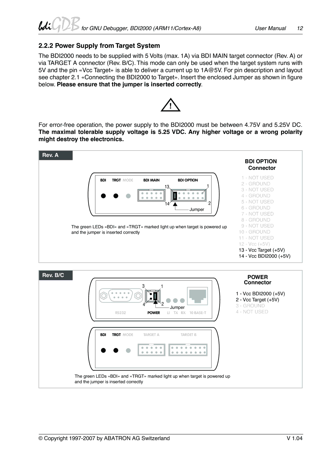
The BDI2000 needs to be supplied with 5 Volts (max. 1A) via BDI MAIN target connector (Rev. A) or via TARGET A connector (Rev. B/C). This mode can only be used when the target system runs with 5V and the pin «Vcc Target» is able to deliver a current up to 1A@5V. For pin description and layout see chapter 2.1 «Connecting the BDI2000 to Target». Insert the enclosed Jumper as shown in figure below. Please ensure that the jumper is inserted correctly.
!
For
The maximal tolerable supply voltage is 5.25 VDC. Any higher voltage or a wrong polarity might destroy the electronics.
Rev. A
BDI TRGT MODE | BDI MAIN |
| BDI OPTION | ||||||
| 13 | 1 | |||||||
|
|
|
|
|
|
|
|
|
|
|
|
|
|
|
|
|
|
|
|
|
|
|
|
|
|
|
|
|
|
|
|
|
|
|
|
|
|
|
|
142
![]() Jumper
Jumper
The green LEDs «BDI» and «TRGT» marked light up when target is powered up and the jumper is inserted correctly
BDI OPTION
Connector
1 - NOT USED
2 - GROUND
3 - NOT USED
4 - GROUND
5 - NOT USED
6 - GROUND
7 - NOT USED
8 - GROUND
9 - NOT USED
10 - GROUND
11 - NOT USED
12 - Vcc (+5V)
13 - Vcc Target (+5V)
14 - Vcc BDI2000 (+5V)
Rev. B/C
31
4 |
| 2 | Jumper |
|
|
|
|
| |
RS232 | POWER | LI | TX RX | 10 |
POWER
Connector
1 - Vcc BDI2000 (+5V)
2 - Vcc Target (+5V)
3 - GROUND
4 - NOT USED
| BDI TRGT MODE | TARGET A |
| TARGET B |
| |||||
|
|
|
|
|
|
|
|
|
|
|
|
|
|
|
|
|
|
|
|
|
|
|
|
|
|
|
|
|
|
|
|
|
|
|
|
|
|
|
|
|
|
|
|
The green LEDs «BDI» and «TRGT» marked light up when target is powered up and the jumper is inserted correctly
© Copyright | V 1.04 |