bdiGDB for GNU Debugger, BDI2000 | User Manual | 5 |
1.2 BDI Configuration
As an initial setup, the IP address of the BDI2000, the IP address of the host with the configuration file and the name of the configuration file is stored within the flash of the BDI2000.
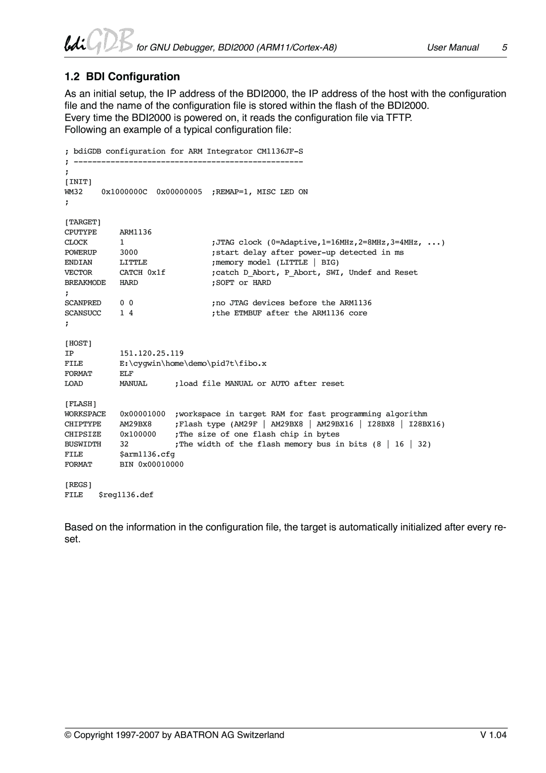
Every time the BDI2000 is powered on, it reads the configuration file via TFTP. Following an example of a typical configuration file:
;bdiGDB configuration for ARM Integrator
;
[INIT]
WM32 0x1000000C 0x00000005 ;REMAP=1, MISC LED ON
[TARGET] |
|
| |
CPUTYPE |
| ARM1136 |
|
CLOCK |
| 1 | ;JTAG clock (0=Adaptive,1=16MHz,2=8MHz,3=4MHz, ...) |
POWERUP |
| 3000 | ;start delay after |
ENDIAN |
| LITTLE | ;memory model (LITTLE BIG) |
VECTOR |
| CATCH 0x1f | ;catch D_Abort, P_Abort, SWI, Undef and Reset |
BREAKMODE | HARD | ;SOFT or HARD | |
; |
|
|
|
SCANPRED | 0 0 | ;no JTAG devices before the ARM1136 | |
SCANSUCC | 1 4 | ;the ETMBUF after the ARM1136 core | |
; |
|
|
|
[HOST] |
|
|
|
IP |
| 151.120.25.119 | |
FILE |
| E:\cygwin\home\demo\pid7t\fibo.x | |
FORMAT |
| ELF |
|
LOAD |
| MANUAL | ;load file MANUAL or AUTO after reset |
[FLASH] |
|
|
|
WORKSPACE | 0x00001000 | ;workspace in target RAM for fast programming algorithm | |
CHIPTYPE | AM29BX8 | ;Flash type (AM29F AM29BX8 AM29BX16 I28BX8 I28BX16) | |
CHIPSIZE | 0x100000 | ;The size of one flash chip in bytes | |
BUSWIDTH | 32 | ;The width of the flash memory bus in bits (8 16 32) | |
FILE |
| $arm1136.cfg | |
FORMAT |
| BIN 0x00010000 | |
[REGS] |
|
|
|
FILE | $reg1136.def |
| |
Based on the information in the configuration file, the target is automatically initialized after every re- set.
© Copyright | V 1.04 |
