bdiGDB for GNU Debugger, BDI2000 | User Manual 11 |
2.2Connecting the BDI2000 to Power Supply 2.2.1 External Power Supply
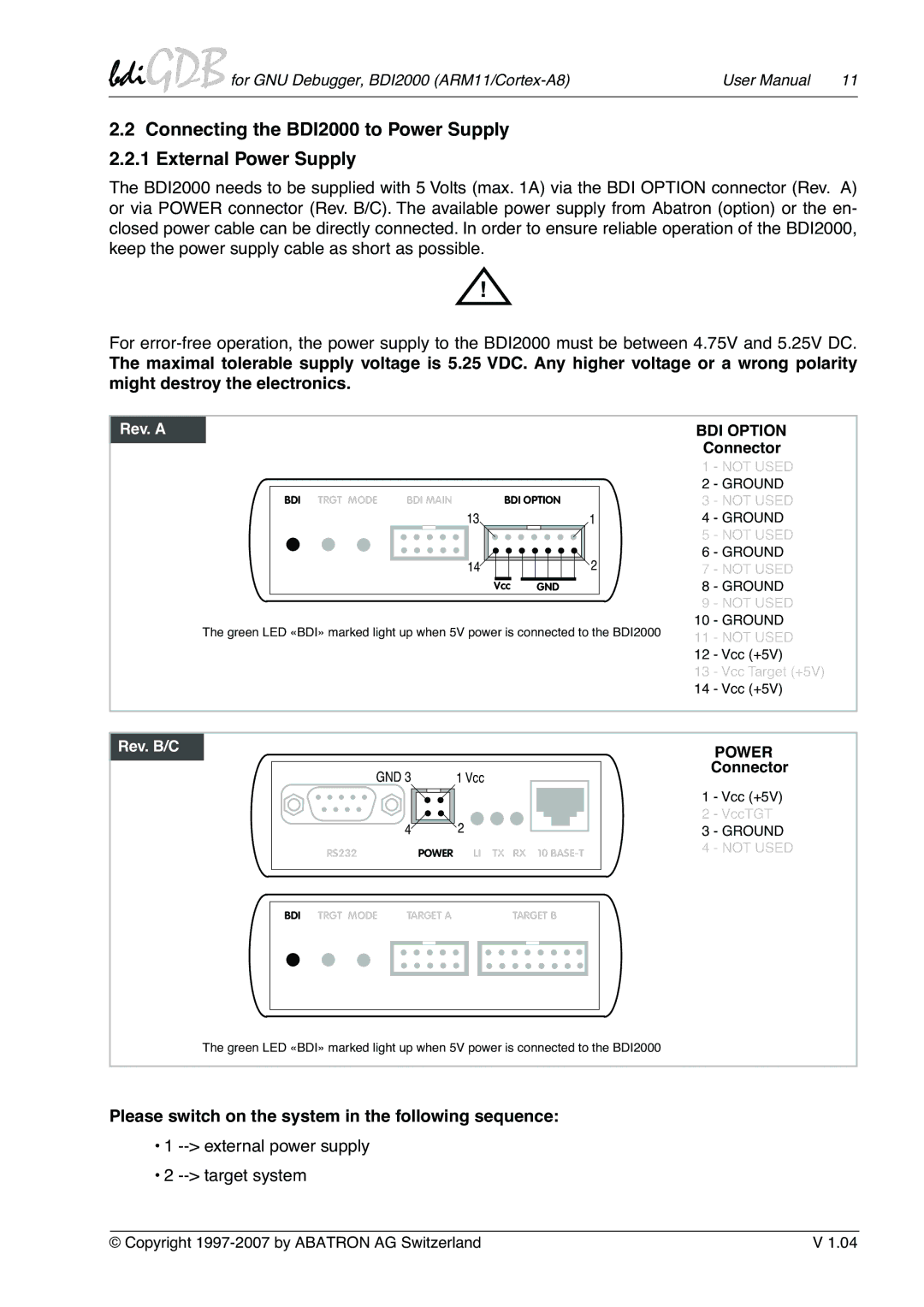
The BDI2000 needs to be supplied with 5 Volts (max. 1A) via the BDI OPTION connector (Rev. A) or via POWER connector (Rev. B/C). The available power supply from Abatron (option) or the en- closed power cable can be directly connected. In order to ensure reliable operation of the BDI2000, keep the power supply cable as short as possible.
!
For
The maximal tolerable supply voltage is 5.25 VDC. Any higher voltage or a wrong polarity might destroy the electronics.
Rev. A
BDI OPTION Connector
|
| 1 | - NOT USED | |
|
| 2 | - GROUND | |
BDI TRGT MODE BDI MAIN | BDI OPTION | 3 | - NOT USED | |
13 | 1 | 4 | - GROUND | |
|
| 5 | - NOT USED | |
14 | 2 | 6 | - GROUND | |
7 | - NOT USED | |||
| Vcc GND | 8 | - GROUND | |
|
| 9 | - NOT USED | |
The green LED «BDI» marked light up when 5V power is connected to the BDI2000 | 10 | - GROUND | ||
11 | - NOT USED | |||
|
| |||
|
| 12 | - Vcc (+5V) | |
|
| 13 | - Vcc Target (+5V) | |
|
| 14 | - Vcc (+5V) | |
Rev. B/CVersion
GND 3 | 1 Vcc |
4 | 2 |
RS232 | POWER LI TX RX 10 |
POWER
Connector
1 - Vcc (+5V)
2 - VccTGT
3 - GROUND
4 - NOT USED
| BDI TRGT MODE | TARGET A |
| TARGET B |
| |||||
|
|
|
|
|
|
|
|
|
|
|
|
|
|
|
|
|
|
|
|
|
|
|
|
|
|
|
|
|
|
|
|
|
|
|
|
|
|
|
|
|
|
|
|
The green LED «BDI» marked light up when 5V power is connected to the BDI2000
Please switch on the system in the following sequence:
•1 --> external power supply
•2 --> target system
© Copyright | V 1.04 |