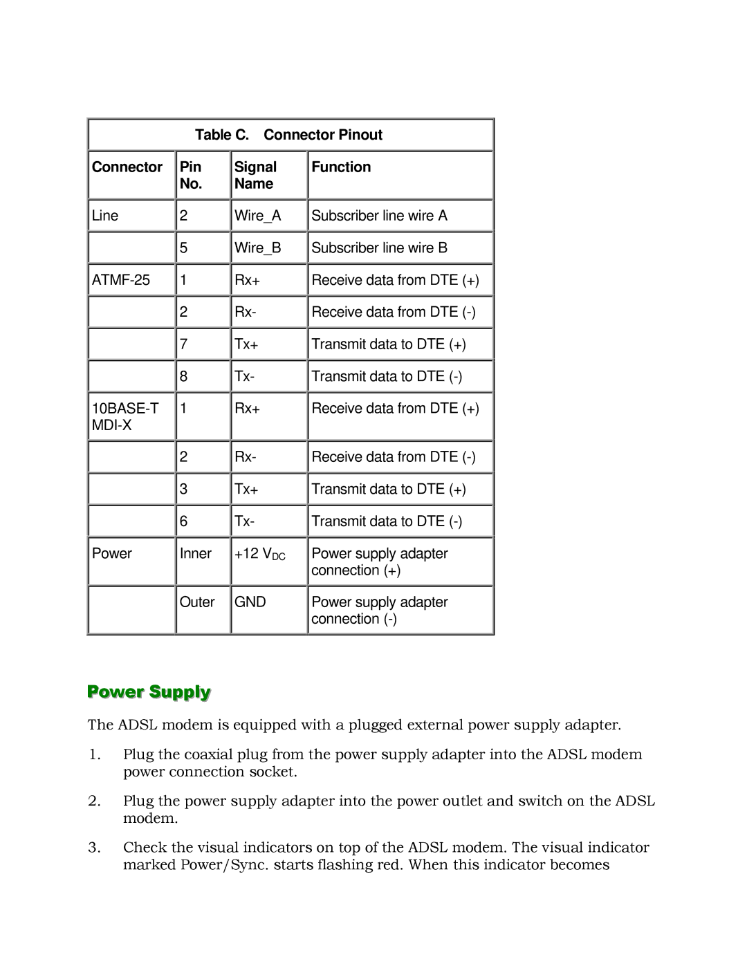
Table C. Connector Pinout
Connector
Line
Power
Pin
No.
![]()
![]() 2
2
![]()
![]() 5
5
![]()
![]() 1
1
![]()
![]() 2
2
![]()
![]() 7
7
![]()
![]() 8 1
8 1
![]()
![]() 2
2
![]()
![]() 3
3
![]()
![]() 6 Inner
6 Inner
Outer
Signal Name
![]()
![]() Wire_A
Wire_A
![]()
![]() Wire_B
Wire_B
![]()
![]() Rx+
Rx+
![]()
![]() Rx-
Rx-
![]()
![]() Tx+
Tx+
![]()
![]() Tx-
Tx-
Rx+
![]()
![]() Rx-
Rx-
![]()
![]() Tx+
Tx+
![]()
![]() Tx-
Tx-
+12 VDC
GND
Function
![]()
![]() Subscriber line wire A
Subscriber line wire A
![]()
![]() Subscriber line wire B
Subscriber line wire B
![]()
![]() Receive data from DTE (+)
Receive data from DTE (+)
![]()
![]() Receive data from DTE
Receive data from DTE
![]()
![]() Transmit data to DTE (+)
Transmit data to DTE (+)
![]()
![]() Transmit data to DTE
Transmit data to DTE
![]()
![]() Receive data from DTE
Receive data from DTE
![]()
![]() Transmit data to DTE (+)
Transmit data to DTE (+)
![]()
![]() Transmit data to DTE
Transmit data to DTE
Power supply adapter connection (+)
Power supply adapter connection
Power Supply
The ADSL modem is equipped with a plugged external power supply adapter.
1.Plug the coaxial plug from the power supply adapter into the ADSL modem power connection socket.
2.Plug the power supply adapter into the power outlet and switch on the ADSL modem.
3.Check the visual indicators on top of the ADSL modem. The visual indicator marked Power/Sync. starts flashing red. When this indicator becomes