x600 Series Layer 3 Gigabit Ethernet Switches Installation Guide
VCS Stacking Modules, Cables, and Connections
The stacks are connected via the stacking ports on the VCS Stacking Modules
The following cables are used to connect the stacking ports of x600 series switches:
High Speed Stacking Cables (0.5 meter) - StackXG/0.5
High Speed Stacking Cables (1.0 meter) - StackXG/1
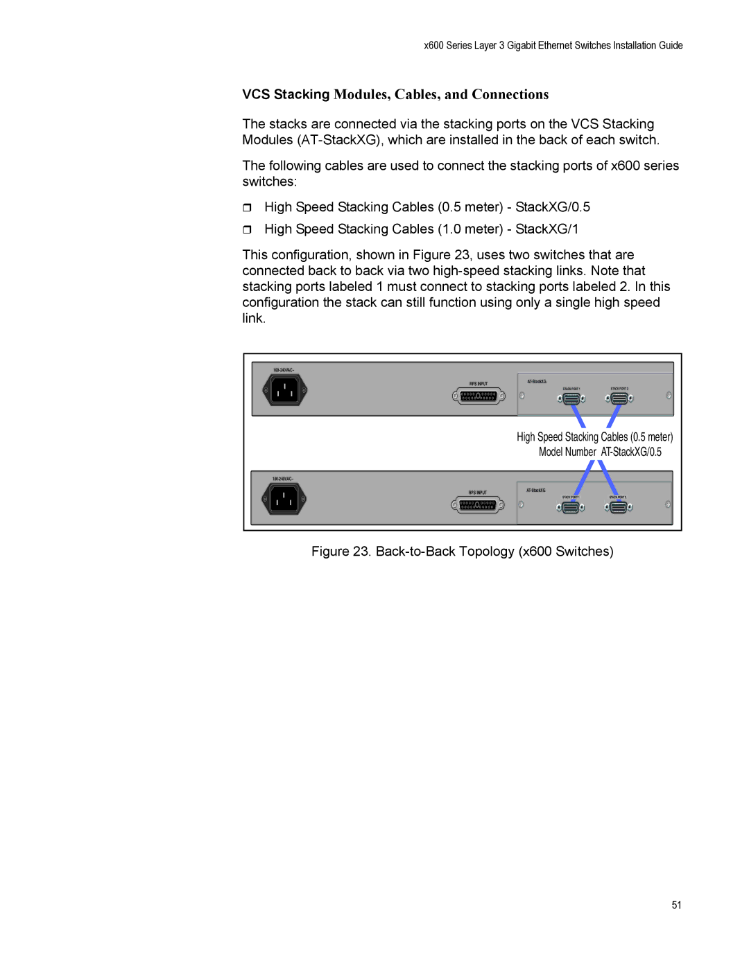
This configuration, shown in Figure 23, uses two switches that are connected back to back via two
RPS INPUT | |
|
STACK PORT 1 | STACK PORT 2 |
High Speed Stacking Cables (0.5 meter)
Model Number
RPS INPUT |
STACK PORT 1 | STACK PORT 2 |
Figure 23. Back-to-Back Topology (x600 Switches)
51