x600 Layer 3 Gigabit Ethernet Switch Installation Guide
Installing the Switches in an Equipment Rack
Perform the following procedure to install each switch in a standard
Note
Steps 1, 2, and 3 are optional. These steps provide instructions on how to remove the
1.Place the switch upside down on a level, secure surface.
2.Using a
Figure 30. Removing the Feet
3.Turn the switch over.
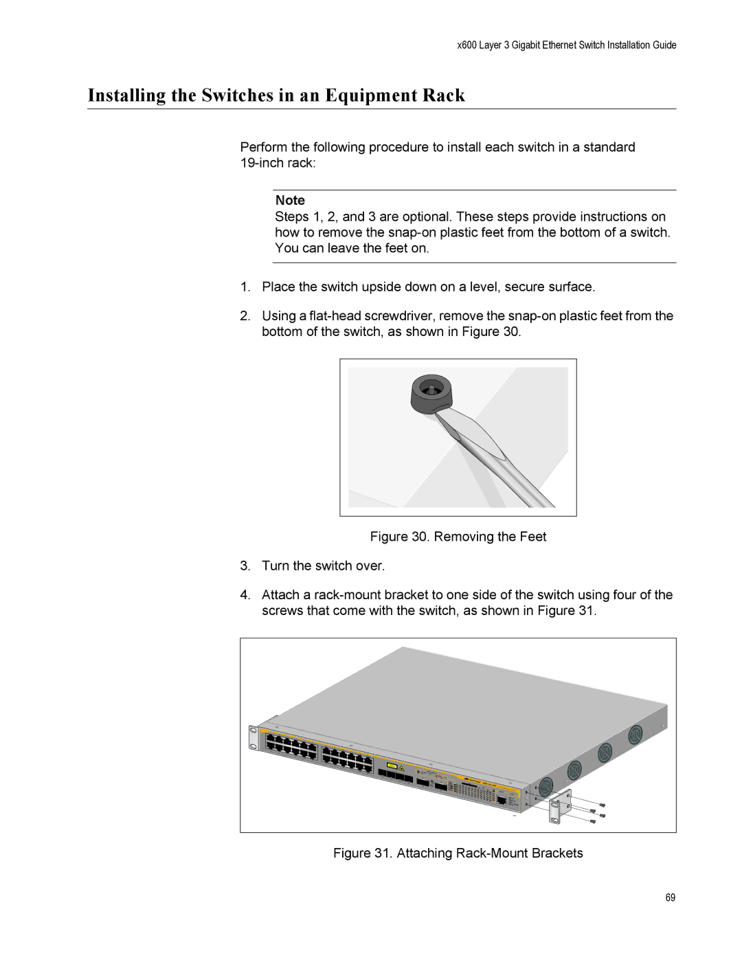
4.Attach a rack-mount bracket to one side of the switch using four of the screws that come with the switch, as shown in Figure 31.
1 |
|
|
|
|
|
|
|
|
|
|
|
|
|
|
|
|
|
|
|
|
|
|
3 |
|
|
|
|
|
|
|
|
|
|
|
|
|
|
|
|
|
|
|
|
|
|
5 |
|
|
|
|
|
|
|
|
|
|
|
|
|
|
|
|
|
|
|
|
|
|
7 |
|
|
|
|
|
|
|
|
|
|
|
|
|
|
|
|
|
|
|
|
|
|
| 9 |
|
|
|
|
|
|
|
|
|
|
|
|
|
|
|
|
|
|
|
|
|
| 11 |
|
|
|
|
|
|
|
|
|
|
|
|
|
|
|
|
|
|
|
|
|
| 13 |
|
|
|
|
|
|
|
|
|
|
|
|
|
|
|
|
|
|
|
|
|
| 15 |
|
|
|
|
|
|
|
|
|
|
|
|
|
|
|
|
|
|
|
|
|
2 | 17 |
|
|
|
|
|
|
|
|
|
|
|
|
|
|
|
|
|
|
|
|
|
4 | 19 |
|
|
|
|
|
|
|
|
|
|
|
|
|
|
|
|
|
|
|
|
|
6 | 21R |
|
|
|
|
|
|
|
|
|
|
|
|
|
|
|
|
|
|
|
|
|
8 | 23R |
|
|
|
|
|
|
|
|
|
|
|
|
|
|
|
|
|
|
|
|
|
| 10 |
|
|
|
|
|
|
|
|
|
|
|
|
|
|
|
|
|
|
|
|
|
| 12 |
|
|
|
|
|
|
|
|
|
|
|
|
|
|
|
|
|
|
|
|
|
| 14 |
|
|
|
|
|
|
|
|
|
|
|
|
|
|
|
|
|
|
|
|
|
| 16 |
|
|
|
|
|
|
|
|
|
|
|
|
|
|
|
|
|
|
|
|
|
| 18 |
|
|
|
|
|
|
|
|
|
|
|
|
|
|
|
|
|
|
|
|
|
| 20 |
|
|
|
|
|
|
|
|
|
|
|
|
|
|
|
|
|
|
|
|
|
| 22R | 1000 | LINK / | PORT |
|
|
|
|
|
|
|
|
|
|
|
|
|
|
|
|
|
|
| 24R | FDX | ACTACTIVITY |
|
|
|
|
|
|
|
|
|
|
|
|
|
|
|
|
|
| |
|
| 21 |
| 10/100 | LINK / |
|
|
|
|
|
|
|
|
|
|
|
|
|
|
|
|
|
|
|
| HDX / | ACT |
|
|
|
|
|
|
|
|
|
|
|
|
|
|
|
| ||
|
| 22 |
|
| COL |
|
|
|
|
|
|
|
|
|
|
|
|
|
|
|
| |
|
| 23 |
|
|
| STACK |
|
|
|
|
|
|
|
| x600- |
|
|
|
|
|
| |
|
| 24 |
|
|
|
|
|
| SD |
|
|
|
| 24Ts/XP |
|
|
|
| ||||
|
| 25 |
|
| 1 | 3 | 5 | 7 |
|
|
|
|
|
|
|
| ||||||
|
|
|
|
|
| 9 | 11 |
|
|
|
|
| Layer 3 | Gigabit |
|
| ||||||
|
|
|
|
| 26 |
|
|
|
|
|
| 13 | 15 | 17 | 19 |
|
| SFP |
| Ethenet Switch | ||
|
|
|
|
|
| 2 |
|
|
|
|
|
|
|
|
| 21R | 23R | CONSOLE |
|
| ||
|
|
|
|
|
| 4 | 6 | 8 |
|
|
|
|
|
|
|
|
|
|
| STATUS |
| |
|
|
|
|
|
|
|
|
|
| 10 | 12 | 14 | 16 |
|
|
|
|
|
|
|
|
|
|
|
|
|
|
|
|
|
|
|
|
| 18 | 20 |
|
|
|
|
| FAULT |
| ||
|
|
|
|
|
|
|
|
|
|
|
|
|
|
|
| 22R 24R |
|
| MASTER |
| ||
|
|
|
|
|
|
|
|
|
|
|
|
|
|
|
|
|
|
|
|
| RPS |
|
|
|
|
|
|
|
|
|
|
|
|
|
|
|
|
|
|
|
|
|
| PWR | RESET |
|
|
|
|
|
|
|
|
|
|
|
|
|
|
|
|
|
|
|
|
| 1327 | |
Figure 31. Attaching Rack-Mount Brackets
69