Chapter 1: Overview
Table 3.
LED | Function | State | Description | |
|
|
|
| |
|
|
|
| |
|
|
|
| |
|
| Off | There is no powered device detected. | |
|
|
|
| |
|
| Solid | The | |
| Power over | Green | and the port is providing power to it. | |
PoE2 | Ethernet |
|
| |
Solid | The port is experiencing a problem | |||
Status | ||||
| Amber | providing PoE to the | ||
|
| |||
|
|
|
| |
|
| Flashing | The port is connected to a powered | |
|
| Amber | device but providing power to it would | |
|
|
| exceed the maximum PoE power | |
|
|
| budget of the switch. | |
|
|
|
|
1.The Duplex Mode and Collisions LED is present on all the x600 switches except for the
2.The PoE LED is only present on the
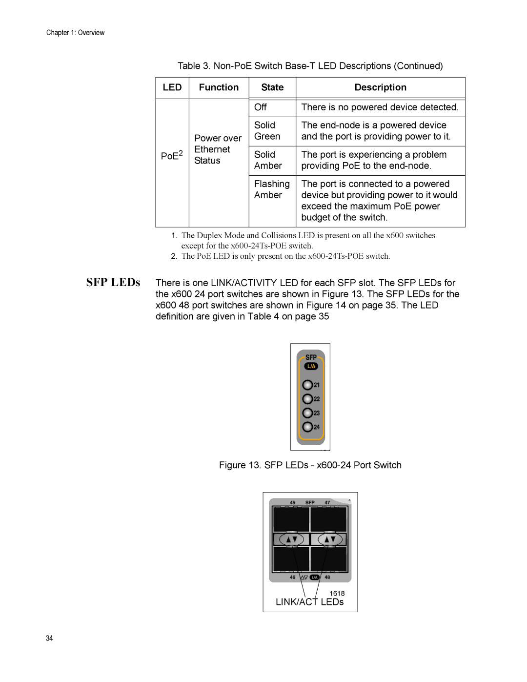
SFP LEDs There is one LINK/ACTIVITY LED for each SFP slot. The SFP LEDs for the x600 24 port switches are shown in Figure 13. The SFP LEDs for the x600 48 port switches are shown in Figure 14 on page 35. The LED definition are given in Table 4 on page 35
SFP
L/A
![]() 21
21
![]() 22
22
![]() 23
23 ![]() 24
24
161
Figure 13. SFP LEDs - x600-24 Port Switch
45 | SFP | 47 |
46 | L/A | 48 |
|
| 1618 |
LINK/ACT LEDs | ||
34