Chapter 2: Virtual Chassis Stacking
management VLAN ID and IP address, use the SHOW STACK command.
Stack Member Identification
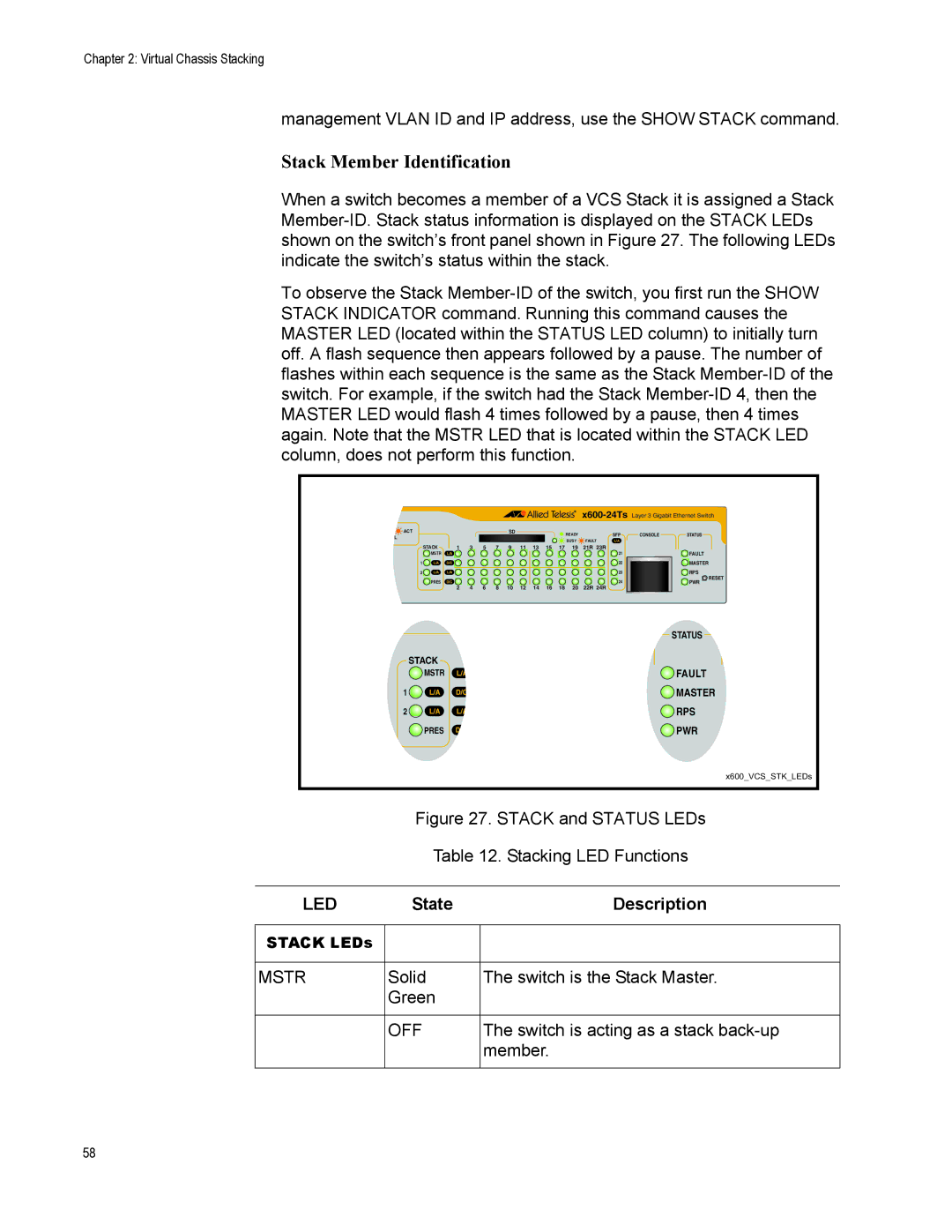
When a switch becomes a member of a VCS Stack it is assigned a Stack Member-ID. Stack status information is displayed on the STACK LEDs shown on the switch’s front panel shown in Figure 27. The following LEDs indicate the switch’s status within the stack.
To observe the Stack Member-ID of the switch, you first run the SHOW STACK INDICATOR command. Running this command causes the MASTER LED (located within the STATUS LED column) to initially turn off. A flash sequence then appears followed by a pause. The number of flashes within each sequence is the same as the Stack Member-ID of the switch. For example, if the switch had the Stack Member-ID 4, then the MASTER LED would flash 4 times followed by a pause, then 4 times again. Note that the MSTR LED that is located within the STACK LED column, does not perform this function.
x600-24TsLayer 3 Gigabit Ethernet Switch
ACT | | | | | | SD | | | | | READY | | SFP | CONSOLE | STATUS |
OL | | | | | | | | | | | |
| | | | | | | | | | BUSY | FAULT | L/A | | |
| | | | | | | | | | | | |
| STACK | 1 | 3 | 5 | 7 | 9 | 11 | 13 | 15 | 17 | 19 | 21R 23R | | | |
| MSTR | L/A | | | | | | | | | | | 21 | | FAULT |
1 | L/A | D/C | | | | | | | | | | | 22 | | MASTER |
2 | L/A | L/A | | | | | | | | | | | 23 | | RPS |
| | | | | | | | | | | | | | | RESET |
| PRES | D/C | | | | | | | | | | | 24 | | PWR |
| | 2 | 4 | 6 | 8 | 10 | 12 | 14 | 16 | 18 | 20 | 22R 24R | | | |
| | | | | | | | STATUS |
| | | | | | | |
| | | | | | | | |
| | | | STACK | | | |
| | | | MSTR | L/A | FAULT |
| | 1 | L/A | D/C | MASTER |
| | 2 | L/A | L/A | RPS |
| | | | PRES | D/C | PWR |
| | | | | | | | x600_VCS_STK_LEDs |
| | | | | | | |
| | | | Figure 27. STACK and STATUS LEDs |
| | | | Table 12. Stacking LED Functions |
| | | | | | | | | |
| LED | | | State | | Description |
| | | | | | | | | |
STACK LEDs | | | | | | | | |
| | | | | | | | | |
MSTR | Solid | | The switch is the Stack Master. |
| | Green | | | |
| | | | | | | | | |
| | OFF | | The switch is acting as a stack back-up |
| | | | | | | | member. |
| | | | | | | | | |