Chapter 4: Cabling the Network Ports
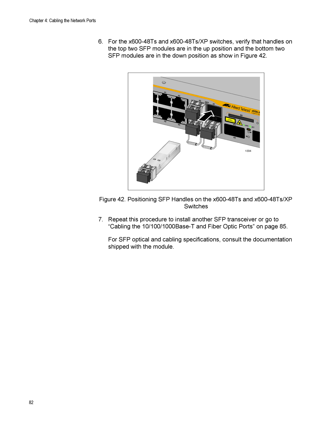
6.For the
41 |
|
|
|
|
|
|
|
|
| 43 |
|
|
|
|
|
|
|
| SFP | 47 |
|
|
|
|
|
|
|
|
|
|
|
|
|
| |
|
|
|
|
|
|
| ||
|
|
|
|
| SD |
| Layer 3 | Gig |
|
|
|
|
|
|
|
| |
|
| CLASS | 1 |
|
|
|
| |
42 |
| LASER |
|
|
|
|
| |
|
| PRODUCT |
|
|
|
| ||
| 44 |
|
| XFP |
| LINK / | ACT |
|
|
|
|
|
|
|
| ||
|
|
|
|
|
|
|
| |
|
|
|
|
|
| L/A |
|
|
|
|
|
| 49 |
|
|
|
|
|
|
|
|
|
| 1334 |
|
|
Figure 42. Positioning SFP Handles on the x600-48Ts and x600-48Ts/XP
Switches
7.Repeat this procedure to install another SFP transceiver or go to “Cabling the 10/100/1000Base-T and Fiber Optic Ports” on page 85.
For SFP optical and cabling specifications, consult the documentation shipped with the module.
82
