Chapter 1: Overview
System STATUS LEDs
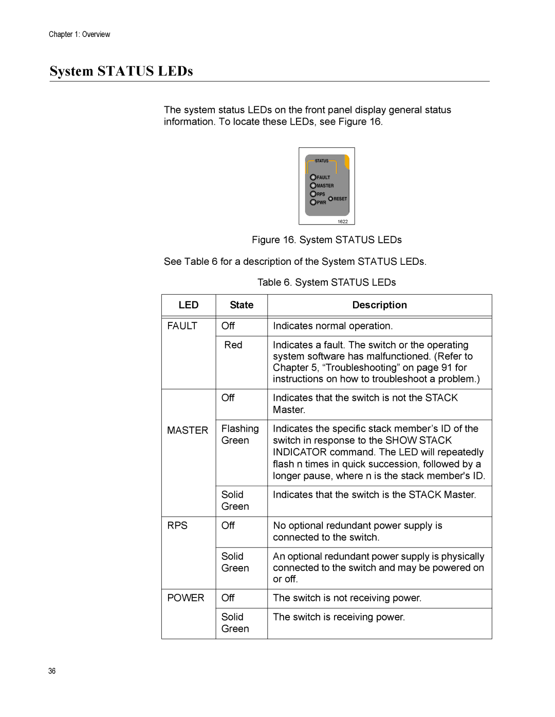
The system status LEDs on the front panel display general status information. To locate these LEDs, see Figure 16.
STATUS
![]() FAULT
FAULT
![]() MASTER
MASTER
![]() RPS
RPS
![]() RESET
RESET
![]() PWR
PWR
1622
Figure 16. System STATUS LEDs
See Table 6 for a description of the System STATUS LEDs.
Table 6. System STATUS LEDs
LED | State | Description |
|
|
|
|
|
|
FAULT | Off | Indicates normal operation. |
|
|
|
| Red | Indicates a fault. The switch or the operating |
|
| system software has malfunctioned. (Refer to |
|
| Chapter 5, “Troubleshooting” on page 91 for |
|
| instructions on how to troubleshoot a problem.) |
|
|
|
| Off | Indicates that the switch is not the STACK |
|
| Master. |
|
|
|
MASTER | Flashing | Indicates the specific stack member’s ID of the |
| Green | switch in response to the SHOW STACK |
|
| INDICATOR command. The LED will repeatedly |
|
| flash n times in quick succession, followed by a |
|
| longer pause, where n is the stack member's ID. |
|
|
|
| Solid | Indicates that the switch is the STACK Master. |
| Green |
|
|
|
|
RPS | Off | No optional redundant power supply is |
|
| connected to the switch. |
|
|
|
| Solid | An optional redundant power supply is physically |
| Green | connected to the switch and may be powered on |
|
| or off. |
|
|
|
POWER | Off | The switch is not receiving power. |
|
|
|
| Solid | The switch is receiving power. |
| Green |
|
|
|
|
36