Appendix A: Technical Specifications
AT-RPS3204 21-pin D-combo Port and Connector Pinouts
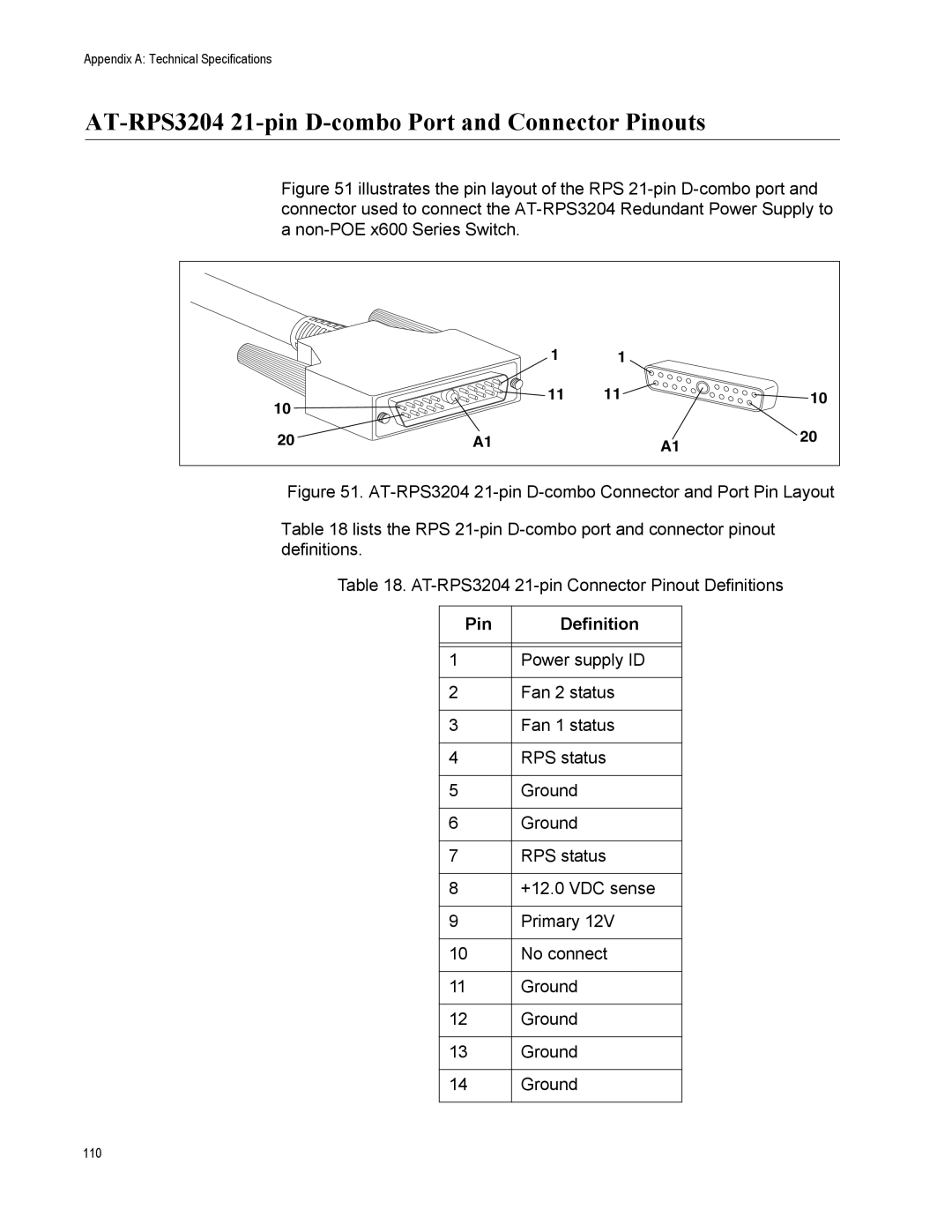
Figure 51 illustrates the pin layout of the RPS 21-pin D-combo port and connector used to connect the AT-RPS3204 Redundant Power Supply to a non-POE x600 Series Switch.
| 1 | 1 |
|
|
10 | 11 | 11 |
| 10 |
|
|
|
| |
20 | A1 |
| A1 | 20 |
|
|
Figure 51. AT-RPS3204 21-pin D-combo Connector and Port Pin Layout
Table 18 lists the RPS 21-pin D-combo port and connector pinout definitions.
Table 18. AT-RPS3204 21-pin Connector Pinout Definitions
Pin | Definition |
|
|
|
|
1 | Power supply ID |
|
|
2 | Fan 2 status |
|
|
3 | Fan 1 status |
|
|
4 | RPS status |
|
|
5 | Ground |
|
|
6 | Ground |
|
|
7 | RPS status |
|
|
8 | +12.0 VDC sense |
|
|
9 | Primary 12V |
|
|
10 | No connect |
|
|
11 | Ground |
|
|
12 | Ground |
|
|
13 | Ground |
|
|
14 | Ground |
|
|
110
