|
| x600 Series Layer 3 Gigabit Ethernet Switches Installation Guide |
|
|
|
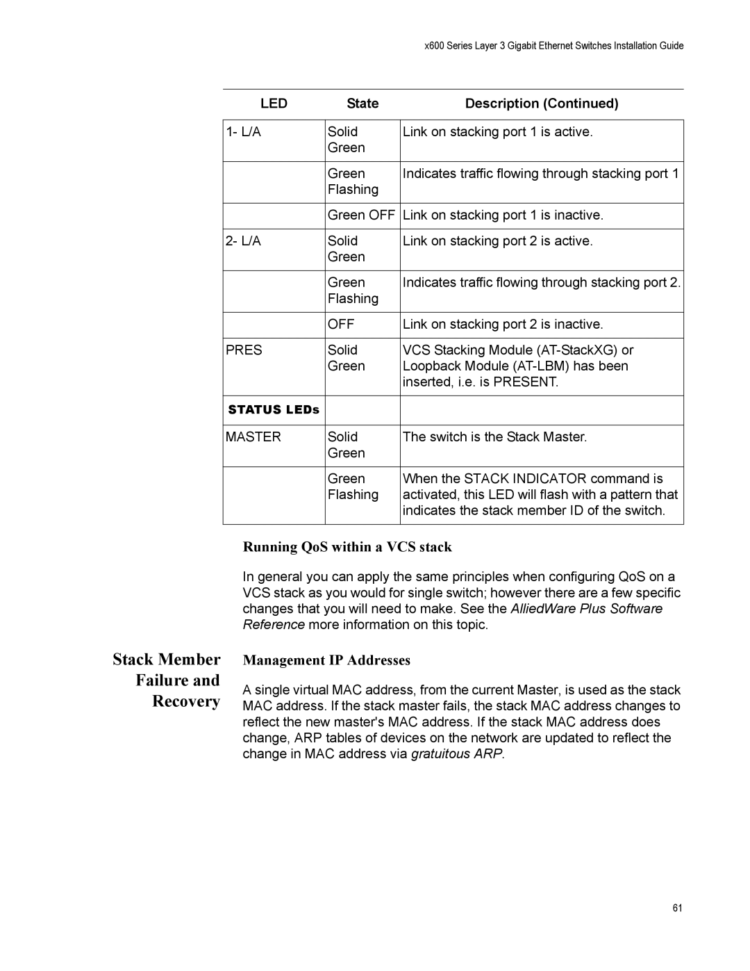
LED | State | Description (Continued) |
|
|
|
1- L/A | Solid | Link on stacking port 1 is active. |
| Green |
|
|
|
|
| Green | Indicates traffic flowing through stacking port 1 |
| Flashing |
|
|
|
|
| Green OFF | Link on stacking port 1 is inactive. |
|
|
|
2- L/A | Solid | Link on stacking port 2 is active. |
| Green |
|
|
|
|
| Green | Indicates traffic flowing through stacking port 2. |
| Flashing |
|
|
|
|
| OFF | Link on stacking port 2 is inactive. |
|
|
|
PRES | Solid | VCS Stacking Module |
| Green | Loopback Module |
|
| inserted, i.e. is PRESENT. |
|
|
|
STATUS LEDs |
|
|
|
|
|
MASTER | Solid | The switch is the Stack Master. |
| Green |
|
|
|
|
| Green | When the STACK INDICATOR command is |
| Flashing | activated, this LED will flash with a pattern that |
|
| indicates the stack member ID of the switch. |
|
|
|
Running QoS within a VCS stack
In general you can apply the same principles when configuring QoS on a VCS stack as you would for single switch; however there are a few specific changes that you will need to make. See the AlliedWare Plus Software Reference more information on this topic.
Stack Member
Failure and
Recovery
Management IP Addresses
A single virtual MAC address, from the current Master, is used as the stack MAC address. If the stack master fails, the stack MAC address changes to reflect the new master's MAC address. If the stack MAC address does change, ARP tables of devices on the network are updated to reflect the change in MAC address via gratuitous ARP.
61