Chapter 1: Overview
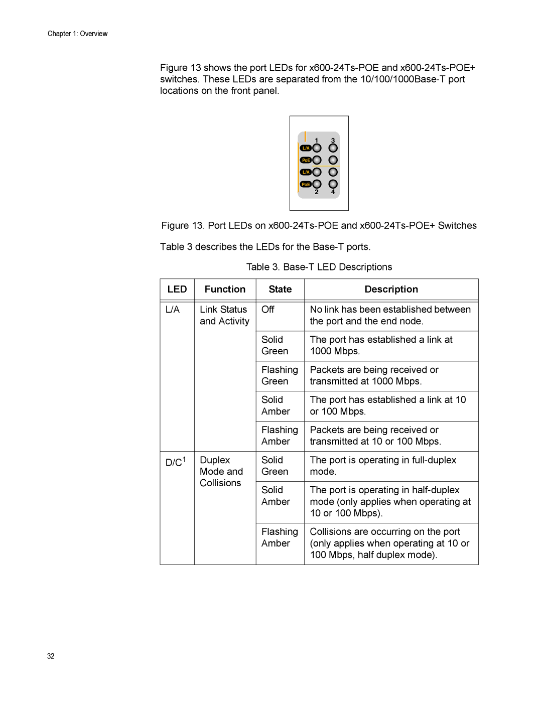
Figure 13 shows the port LEDs for x600-24Ts-POE and x600-24Ts-POE+ switches. These LEDs are separated from the 10/100/1000Base-T port locations on the front panel.
1 3
L/A
PoE ![]()
L/A ![]()
PoE
2 4
Figure 13. Port LEDs on x600-24Ts-POE and x600-24Ts-POE+ Switches
Table 3 describes the LEDs for the Base-T ports.
Table 3. Base-T LED Descriptions
LED | Function | State | Description |
|
|
|
|
|
|
|
|
L/A | Link Status | Off | No link has been established between |
| and Activity |
| the port and the end node. |
|
|
|
|
|
| Solid | The port has established a link at |
|
| Green | 1000 Mbps. |
|
|
|
|
|
| Flashing | Packets are being received or |
|
| Green | transmitted at 1000 Mbps. |
|
|
|
|
|
| Solid | The port has established a link at 10 |
|
| Amber | or 100 Mbps. |
|
|
|
|
|
| Flashing | Packets are being received or |
|
| Amber | transmitted at 10 or 100 Mbps. |
|
|
|
|
D/C1 | Duplex | Solid | The port is operating in |
| Mode and | Green | mode. |
| Collisions |
|
|
| Solid | The port is operating in | |
|
| ||
|
| Amber | mode (only applies when operating at |
|
|
| 10 or 100 Mbps). |
|
|
|
|
|
| Flashing | Collisions are occurring on the port |
|
| Amber | (only applies when operating at 10 or |
|
|
| 100 Mbps, half duplex mode). |
|
|
|
|
32