POEGEM12T2SFP User Manual
2.Installation
2.1.Starting the POEGEM12T2SFP SNMP Managed POE Switches
This section provides a quick start guide for:
•Hardware and Cable Installation
•Management Station Installation
•Software booting and configuration
2.1.1.Hardware and Cable Installation
Please Note:
⇒ Wear a grounding strap to avoid damaging the switch with an electrostatic discharge
⇒Be sure that the power switch is in the ‘OFF’ position before you insert the power cord
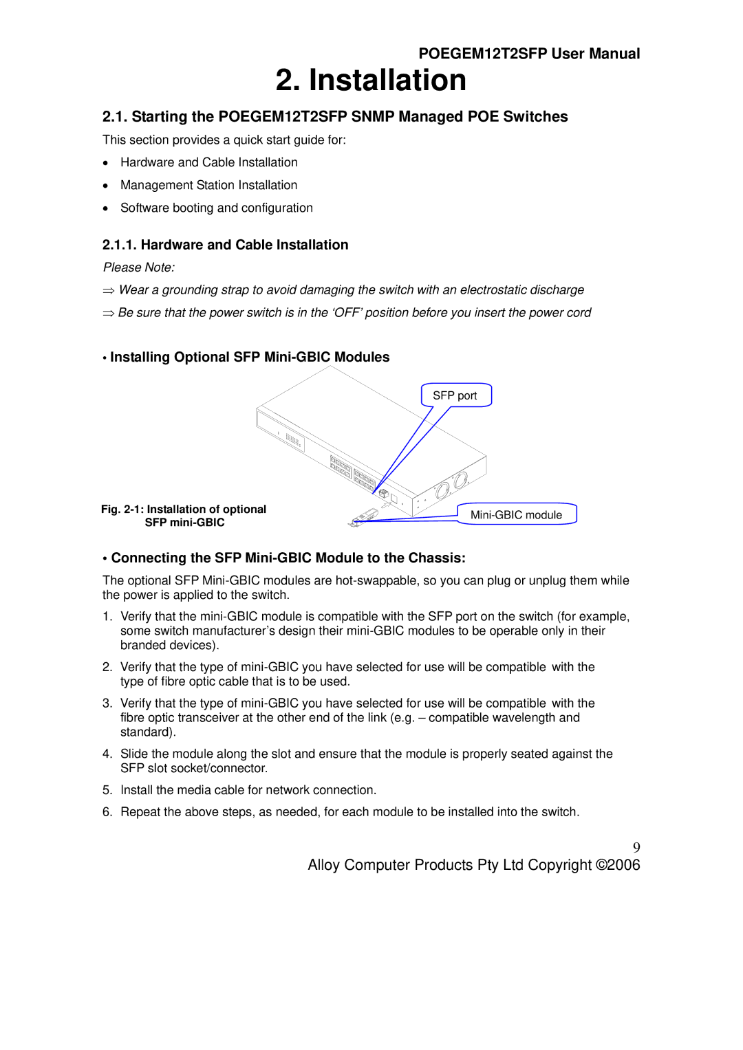
•Installing Optional SFP Mini-GBIC Modules
SFP port
Fig. 2-1: Installation of optional SFP mini-GBIC
• Connecting the SFP Mini-GBIC Module to the Chassis:
The optional SFP
1.Verify that the
2.Verify that the type of
3.Verify that the type of
4.Slide the module along the slot and ensure that the module is properly seated against the SFP slot socket/connector.
5.Install the media cable for network connection.
6.Repeat the above steps, as needed, for each module to be installed into the switch.
9
Alloy Computer Products Pty Ltd Copyright ©2006