American Dryer Corp AD-95 service manual Sail Switch Gas Models Only, Hi-Limit Gas Models Only

Models: AD-95

1 64
Download 64 pages 35.24 Kb
Page 19
Image 19

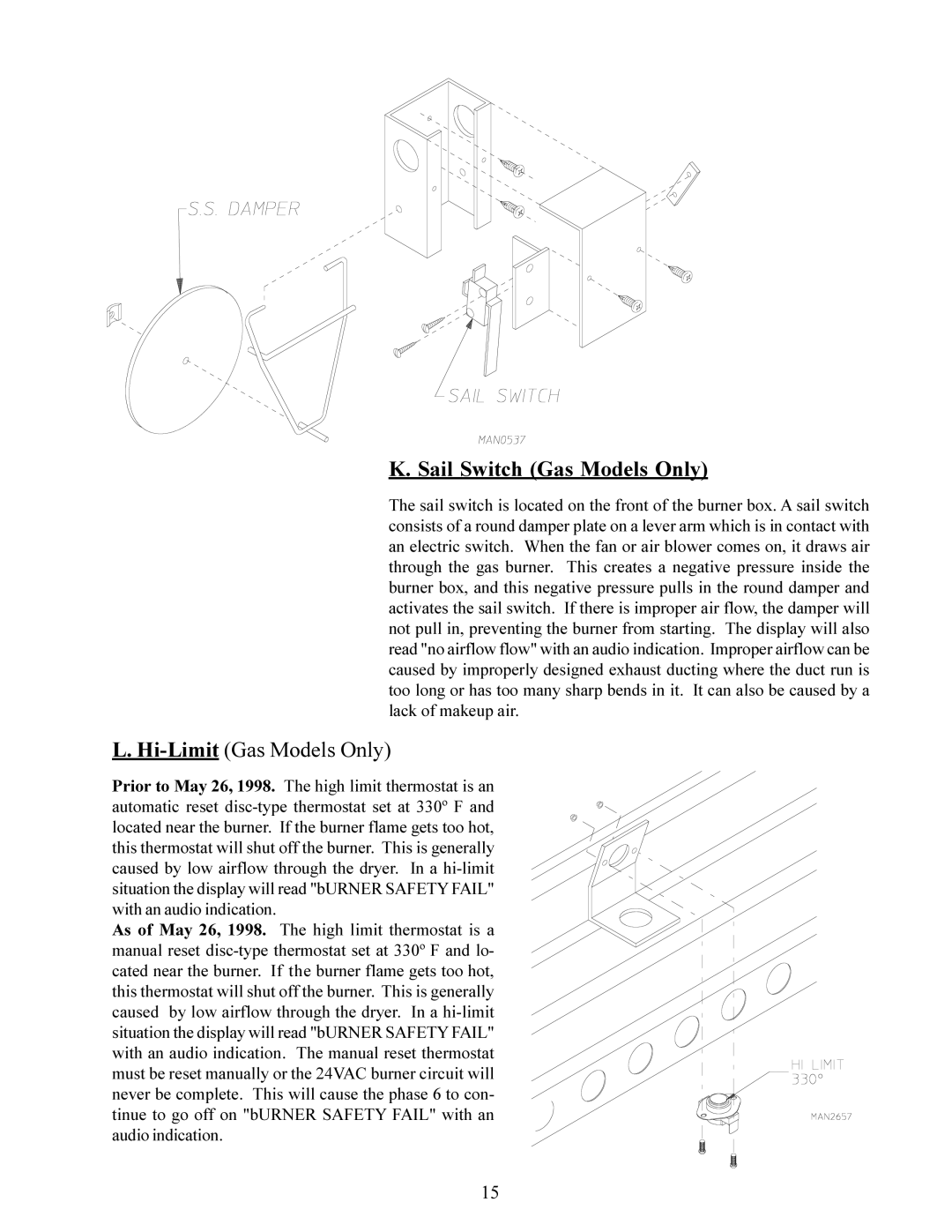
K. Sail Switch (Gas Models Only)

The sail switch is located on the front of the burner box. A sail switch consists of a round damper plate on a lever arm which is in contact with an electric switch. When the fan or air blower comes on, it draws air through the gas burner. This creates a negative pressure inside the burner box, and this negative pressure pulls in the round damper and activates the sail switch. If there is improper air flow, the damper will not pull in, preventing the burner from starting. The display will also read "no airflow flow" with an audio indication. Improper airflow can be caused by improperly designed exhaust ducting where the duct run is too long or has too many sharp bends in it. It can also be caused by a lack of makeup air.

L. Hi-Limit (Gas Models Only)

Prior to May 26, 1998. The high limit thermostat is an automatic reset disc-type thermostat set at 330º F and located near the burner. If the burner flame gets too hot, this thermostat will shut off the burner. This is generally caused by low airflow through the dryer. In a hi-limit situation the display will read "bURNER SAFETY FAIL" with an audio indication.

As of May 26, 1998. The high limit thermostat is a manual reset disc-type thermostat set at 330º F and lo- cated near the burner. If the burner flame gets too hot, this thermostat will shut off the burner. This is generally caused by low airflow through the dryer. In a hi-limit situation the display will read "bURNER SAFETY FAIL" with an audio indication. The manual reset thermostat must be reset manually or the 24VAC burner circuit will never be complete. This will cause the phase 6 to con- tinue to go off on "bURNER SAFETY FAIL" with an audio indication.

15

Page 19
Image 19
American Dryer Corp AD-95 service manual Sail Switch Gas Models Only, Hi-Limit Gas Models Only