Input/Output Wiring – Dual Mains
The UPS is designed for single mains installation as default. Follow the below instructions to install the UPS in a
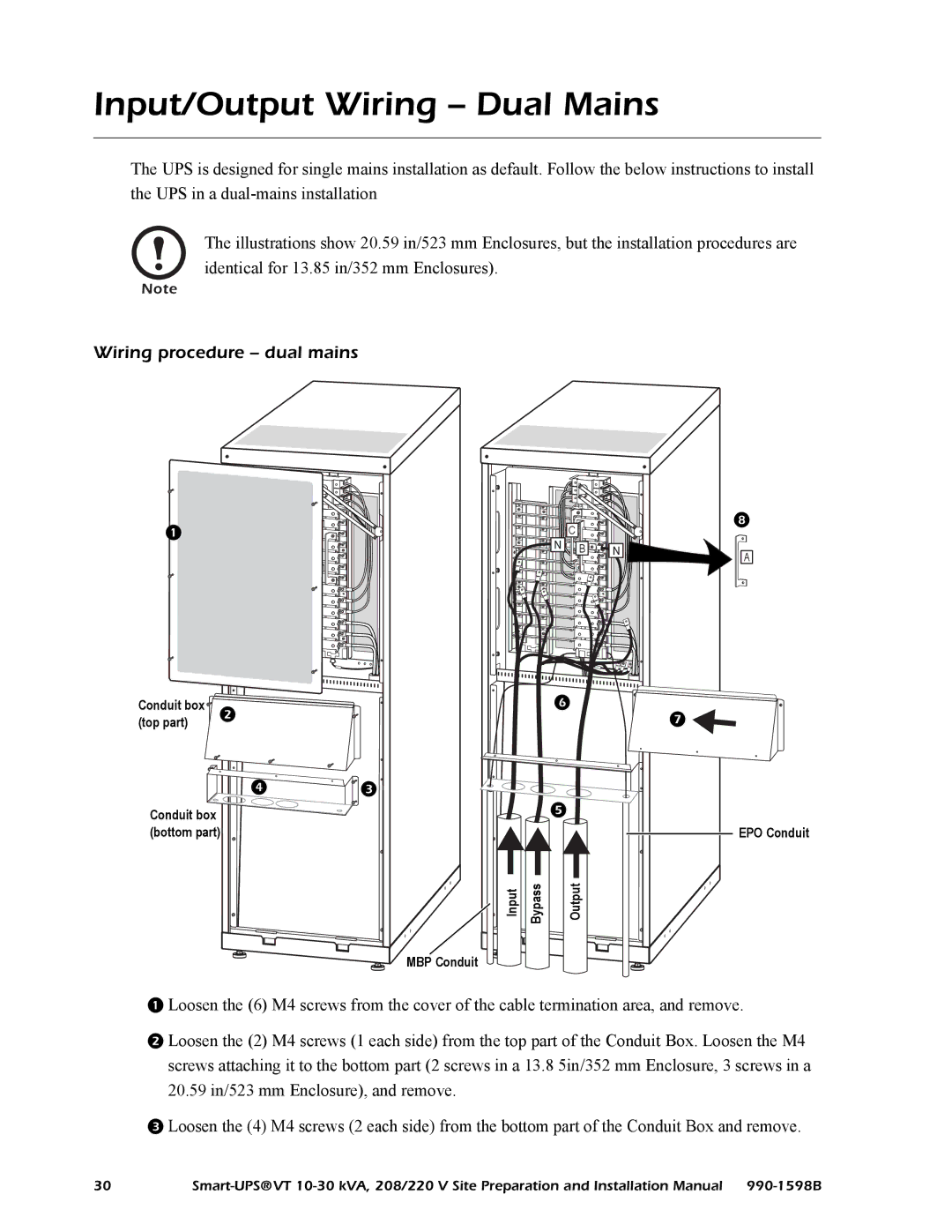
The illustrations show 20.59 in/523 mm Enclosures, but the installation procedures are identical for 13.85 in/352 mm Enclosures).
Note
Wiring procedure – dual mains
| N | C |
| B N | |
|
|
Conduit box | |
| |
(top part) |
|
| |
| | |
|
Conduit box |
|
| |
(bottom part) |
|
| |
|
| Input Bypass | Output |
|
| MBP Conduit |
|
A
![]()
EPO Conduit
Loosen the (6) M4 screws from the cover of the cable termination area, and remove.
Loosen the (2) M4 screws (1 each side) from the top part of the Conduit Box. Loosen the M4 screws attaching it to the bottom part (2 screws in a 13.8 5in/352 mm Enclosure, 3 screws in a 20.59 in/523 mm Enclosure), and remove.
Loosen the (4) M4 screws (2 each side) from the bottom part of the Conduit Box and remove.
30 |